Tooling pressure holding delay equipment

A technology of tooling and equipment, which is applied in the field of tooling pressure holding and delay equipment, can solve the problems of bulky equipment, inability to meet the production requirements of pressure holding and delay time, and short pressure holding and delay time

Active Publication Date: 2020-07-03
WEIFANG LOKOMO PRECISION IND
View PDF7 Cites 0 Cited by
  • Summary
  • Abstract
  • Description
  • Claims
  • Application Information

AI Technical Summary

Problems solved by technology

The pressure-holding delay process requires the tooling with the product to flow into the pressure-holding delay device at a fixed beat, and flow out of the pressure-holding delay device at the same beat. Therefore, the longer the delay required for the holding pressure, the longer the pressure-holding delay device needs The number of tooling that can be accommodated is also greater, and a large number of tooling and pressure-holding delay mechanisms will make the entire equipment bulky, occupy a lot of space, and cannot be connected in series to the production line of flexible line products
Most of the current flexible line pressure holding and delay mechanisms are suitable for occasions with a small number of tooling, that is, they are suitable for the production of products with a short pressure holding and delay time, and cannot meet the production requirements of products with a long pressure holding and delay time

Method used


Image

  • Tooling pressure holding delay equipment
  • Tooling pressure holding delay equipment
  • Tooling pressure holding delay equipment

Examples


Embodiment Construction

[0030] Below in conjunction with accompanying drawing and embodiment, further elaborate the present invention.

[0031] The orientations involved in this specification are all subject to the orientations shown in the drawings, which only represent relative positional relationships, not absolute positional relationships.

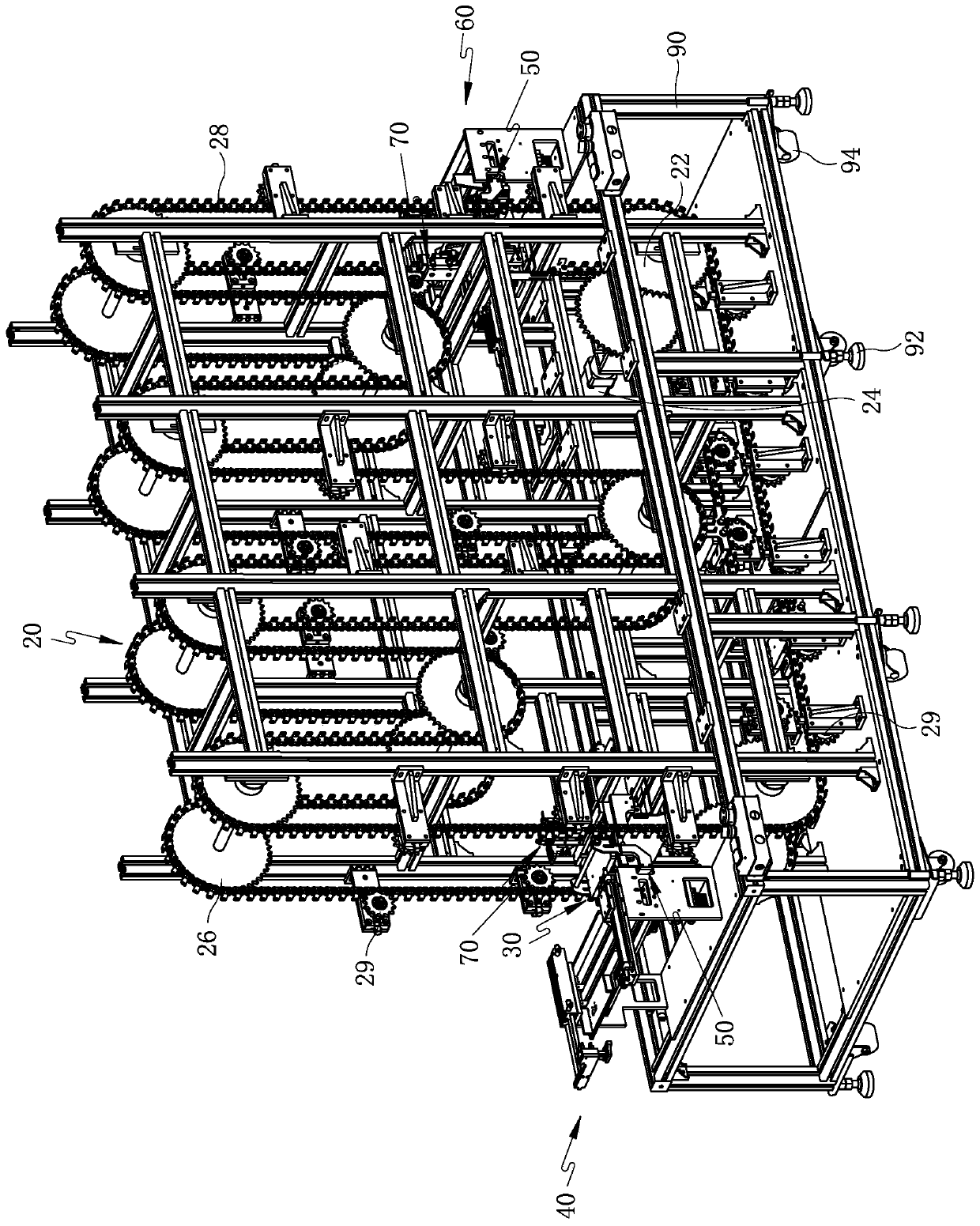
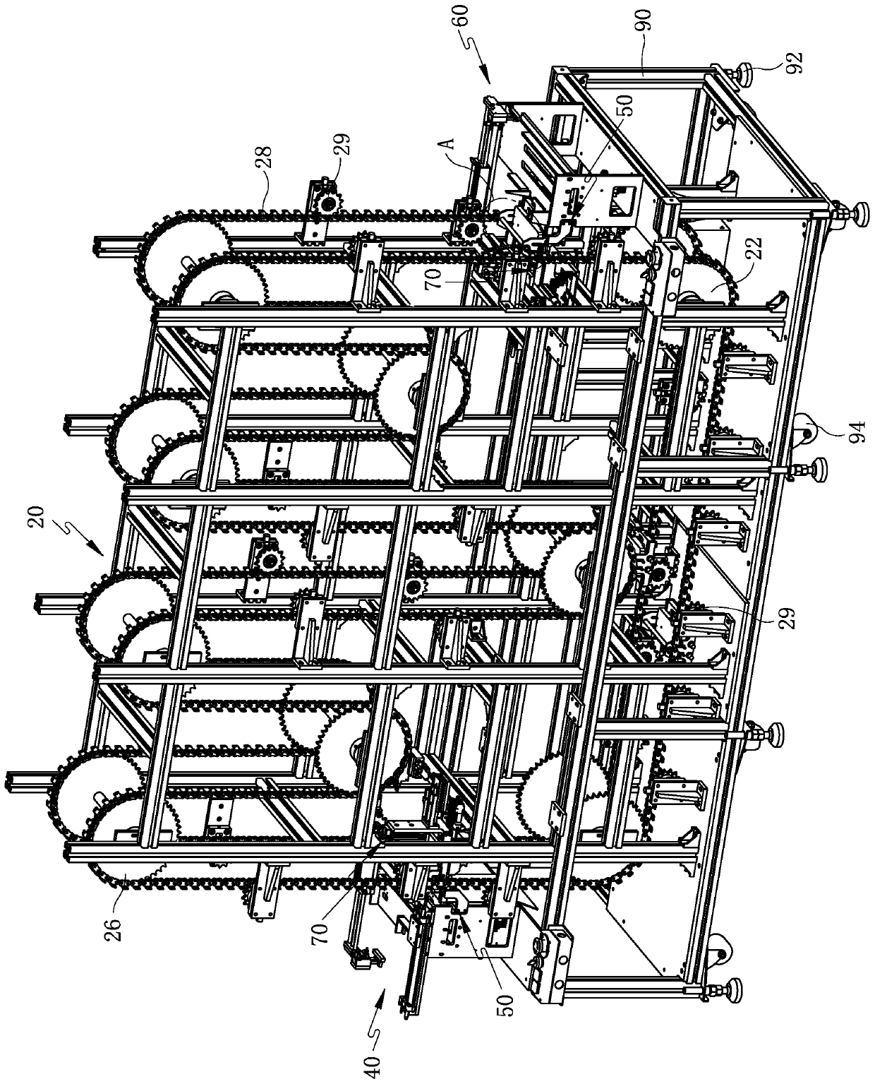
[0032] Such as figure 1 and figure 2 Commonly shown, a tooling pressure maintaining and delaying device includes a frame 90, the frame 90 is a frame structure composed of multiple vertical beams and multiple cross beams, and its cross section is rectangular. A suspension conveying mechanism 20 is installed on the frame 90, and the suspension conveying mechanism 20 comprises a plurality of chain wheel groups installed on the frame 90, and each chain wheel group comprises two sprockets arranged coaxially, and the two sprockets are respectively installed on The two ends of the sprocket shaft, the sprocket shaft is installed on the frame 90 by bearing rotation...


PUM


Abstract

The invention discloses tool pressure maintaining time-delay equipment and relates to the technical field of electronic product production equipment. The tool pressure maintaining time-delay equipmentincludes a rack, multiple chain wheel groups are installed on the rack, each chain wheel group includes two chain wheels which are arranged coaxially, and all the chain wheels on the same side in each chain wheel group are surrounded by a chain; all the chain wheel groups are staggered vertically, and correspondingly the two chains form a structure which is folded several times; a hanging basketwhich is used for placing tools and moves along with the chains is hung between the two chains, and counter weights used for maintaining the pressure of the tools are arranged in the hanging basket; afeeding mechanism used for placing the tools into the hanging bracket and a discharge mechanism used for taking the tools out of the hanging basket are arranged at the two ends of the rack respectively; the two ends of the rack are both provided with a hanging basket positioning mechanism and a counter weight lifting mechanism, wherein each hanging basket positioning mechanism can position the hanging basket after the hanging basket moves in place, and each counter weight lifting mechanism is used for lifting up the counter weights after positioning in order to provide convenience for feedingby the feeding mechanism and discharge by the discharge mechanism. The tool pressure maintaining time-delay equipment in a small size meets the requirement for long pressure maintaining delay time.

Description

technical field [0001] The invention relates to the technical field of electronic product production equipment, in particular to a tooling pressure maintaining and delaying equipment for pressure maintaining and delaying bonding products. Background technique [0002] In the flexible wire bonding assembly process of electronic products, it is often necessary to delay the pressure of the bonded products to ensure the firmness and reliability of the bonding. The pressure holding delay process requires the tooling with the product to flow into the pressure holding delay equipment at a fixed beat, and flow out of the pressure holding delay equipment at the same beat. Therefore, the longer the delay required for the holding pressure, the longer the pressure holding delay equipment needs. The number of tooling that can be accommodated is also greater, and a large number of tooling and pressure holding and delay mechanisms will make the entire equipment bulky and occupy a lot of sp...

Claims


Application Information

Patent Timeline
Patent Type & Authority Patents(China)
IPC IPC(8): B65G17/12B65G17/32B65G21/20B65G41/00B65G47/24B65G47/82
CPCB65G17/12B65G17/323B65G21/2063B65G41/003B65G47/24B65G47/82B65G2203/042
Inventor 丛秉华蒋先锋
Owner WEIFANG LOKOMO PRECISION IND
Why Eureka
Try Eureka