A Sound Field Separation Method Using Sparse Measurements

A separation method and sound field technology, which are applied in the measurement of ultrasonic/sonic/infrasonic waves, measurement devices, instruments, etc., can solve the problems of resolution limitation, affecting the scope of use, and high measurement cost, and achieve the effect of high separation accuracy and spatial resolution.

Active Publication Date: 2021-02-05
SHANGHAI UNIV OF ENG SCI
View PDF7 Cites 0 Cited by
  • Summary
  • Abstract
  • Description
  • Claims
  • Application Information

AI Technical Summary

Problems solved by technology

However, most of these sound field separation methods require sound pressure and particle velocity on two measurement surfaces or a single measurement surface, and their resolution is limited by the sampling theorem, and the measurement cost is high
The sound field separation technology for sound pressure measurement on a single measuring surface proposed by Song Yulai et al. and Mao Jin et al. respectively reduces the number of measuring points to a certain extent, but both methods need to predict the approximate location of the sound source, which affects their scope of application.

Method used


Image

  • A Sound Field Separation Method Using Sparse Measurements
  • A Sound Field Separation Method Using Sparse Measurements
  • A Sound Field Separation Method Using Sparse Measurements

Examples


Embodiment

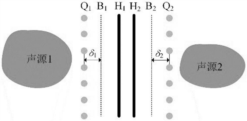
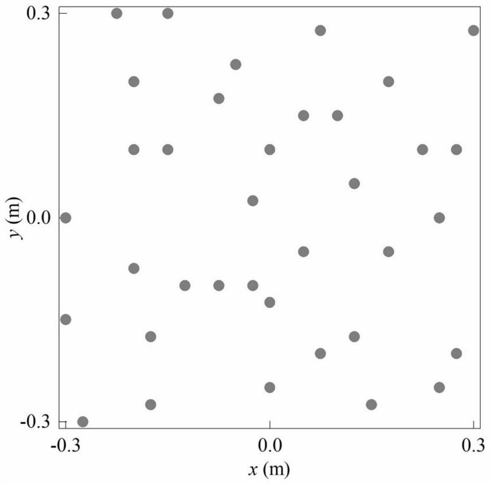
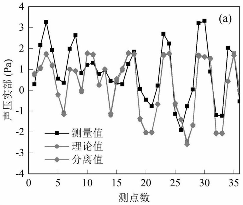
[0040] Example: two pulsating spheres with a radius of 0.01m are used as sound sources, and their surface vibration velocity is 1m / s, and the sound source located at (0.25,0.25,-0.4)m is sound source 1, located at (0.25, The sound source at 0.25, 0.4) m is sound source 2. The measuring surface is located at z H1 = -0.025m and z H2 =0.025m, 36 measuring points are arranged on each measuring surface, the distribution of measuring points is as follows figure 2 As shown, the distance between the two equivalent sound source surfaces and the virtual boundary surface is 0.075m. Gaussian white noise is added to the two measurement surfaces and the signal-to-noise ratio is 30dB. By superimposing the sound pressure signals of sound source 1 and sound source 2 with the point sound source to form a fitted sound field, the sparseness of the sound pressure vector of the fitted sound field is obtained. According to the sound pressure signal and the sparse basis, the sparse solution of th...


PUM


Abstract

The invention relates to a sound field separation method using sparse measurement, and belongs to the technical field of acoustics. It is characterized in that two measurement surfaces are set between multiple sound sources of the sound field to be separated, the sound pressure signals on the measurement surfaces are measured using a random sparse array, and an equivalent sound source surface is arranged on both sides of the measurement surface, etc. A point sound source is arranged on the sound source surface, and the sound pressure signal is fitted to the point sound source by combining the equivalent source principle and the wave superposition principle to form a fitted sound field; the sound pressure of the fitted sound field is obtained through singular value decomposition according to the compressive sensing theory The sparse basis of the vector, and establish the sound field separation model; the measured sound pressure signal and the sparse basis of the fitted sound field sound pressure vector are substituted into the sound field separation model, and the weight coefficient of the sparse basis is obtained by the sparse regularization method, so as to obtain Measure the sound field generated by the sound sources on both sides of the surface to achieve sound field separation. The invention can separate the sound field of the sound source with only a few measuring points, and has high separation precision and spatial resolution.

Description

technical field [0001] The invention relates to a sound field separation method using sparse measurement, and belongs to the technical field of acoustics. Background technique [0002] The sound field separation technology has a wide range of applications in the fields of scattered sound calculation, reflection coefficient measurement, and sound field reconstruction in non-free sound fields. At present, the sound field separation technology mainly includes: the sound field separation technology based on the spatial two-dimensional Fourier transform proposed by Yu Fei et al., the statistical optimal sound field separation technology based on the statistical optimal sound field separation technology proposed by J.Hald et al., and the mirror method sound field separation proposed by F.Jacobsen et al. technology etc. However, most of these sound field separation methods require sound pressure and particle velocity on two measurement surfaces or a single measurement surface, and...

Claims


Application Information

Patent Timeline
Patent Type & Authority Patents(China)
IPC IPC(8): G01H17/00
CPCG01H17/00
Inventor 胡定玉刘馨悦方宇
Owner SHANGHAI UNIV OF ENG SCI
Why Eureka
Try Eureka