Method for determining a distance between two beamlets in a multi-beamlet exposure apparatus

Active Publication Date: 2012-11-22
ASML NETHERLANDS BV
View PDF5 Cites 13 Cited by
  • Summary
  • Abstract
  • Description
  • Claims
  • Application Information

AI Technical Summary

Benefits of technology

[0013]An object of the present invention relates to improving the accuracy of a beam separation measurement between two beamlets in a multi-beamlet lithography system. For this purpose, the present invention provides a method for determining a distance between two charged particle beamlets in a multi-beamlet exposure apparatus provided with a sensor comprising a converter element for converting the energy of charged particles into light and a light sensitive detector, the converter element being provided with a sensor surface area provided with a two-dimensional pattern of beamlet blocking and non-blocking regions, the method comprising: scanning a first beamlet over the two-dimensional pattern; receiving light generated by the converter element in response to charged particles being part of the first beamlet transmitted through the two-dimensional pattern; converting the received light into a first signal by means of the light sensitive detector; shifting the two-dimensional pattern with respect to the first beamlet over a predetermined distance; scanning a second beamlet over the two-dimensional pattern; receiving light generated by the converter element in response to charged particles being part of the second beamlet transmitted through the two-dimensional pattern; converting the received light into a second signal by means of the light sensitive detector; determining the distance between the first beamlet and second beamlet bas

Problems solved by technology

As a result, a substantial amount of

Method used


Image

  • Method for determining a distance between two beamlets in a multi-beamlet exposure apparatus
  • Method for determining a distance between two beamlets in a multi-beamlet exposure apparatus
  • Method for determining a distance between two beamlets in a multi-beamlet exposure apparatus

Examples


Example

[0031]The following is a description of certain embodiments of the invention, given by way of example only and with reference to the drawings.

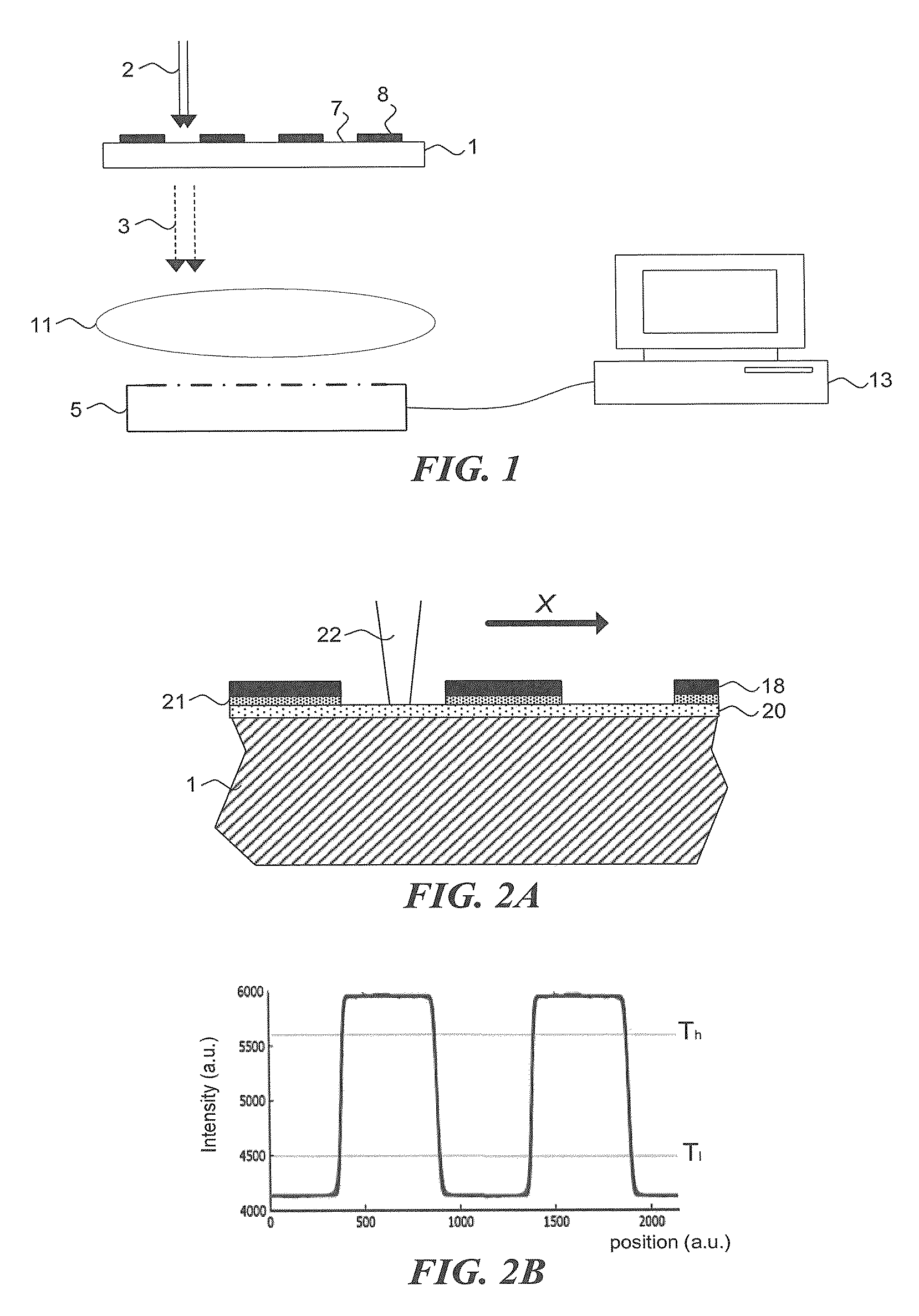
[0032]FIG. 1 schematically shows the operation of a sensor for determining a beam position of charged particle beamlets. The sensor comprises a converter element 1 and a light receptor 5. The converter element is provided with a pattern comprising charged particle blocking regions 8 and charged particle transmissive regions 7, further referred to as non-blocking regions. The converter element 1 is arranged for receiving charged particles 2 and generating photons in response, further referred to as light 3. The light 3 may be directed towards the photon receptor 5 by means of an optical system 11. The photon receptor 5 is communicatively coupled to a calculation unit, e.g. a computer 13 for determining the beam position of charged particles 2.

[0033]The converter element 1 may take the form of a fluorescent element, for example a fluorescent scr...


PUM


Abstract

The invention relates to a method for determining a distance between charged particle beamlets in a multi-beamlet exposure apparatus. The apparatus is provided with a sensor comprising a converter element for converting charged particle energy into light and a light sensitive detector provided with a two-dimensional pattern of beamlet blocking and non-blocking regions. The method comprises scanning a first beamlet over the pattern, receiving light generated by the converter element, and converting the received light into a first signal. Then the two-dimensional pattern and the first beamlet are moved relatively with respect to each other over a predetermined distance. Subsequently, the method comprises scanning a second beamlet over the pattern, receiving light generated by the converter element, and converting the received light into a second signal. Finally, the distance between the first beamlet and second beamlet is determined based on the first signal, the second signal and the predetermined distance.

Description

BACKGROUND OF THE INVENTION[0001]1. Field of the Invention[0002]The present invention relates to a method for determining a distance between two charged particle beamlets in a multi-beamlet exposure apparatus.[0003]2. Description of the Related Art[0004]In order to transfer a pattern onto the target surface, the controllable blocking of beamlets in combination with their movement over the target surface is performed in accordance with modulation information. An example of a multiple charged-particle beamlet lithography system is described in U.S. Pat. No. 6,958,804, which disclosure is herewith incorporated by reference in its entirety.[0005]Such lithography systems can have very large numbers of beamlets, i.e. in the order of 10,000 or higher, for example 13,000. Future designs even envisage numbers in the order of 1,000,000 beamlets. It is a general aim for current electron beam lithography systems to be able to pattern a target surface in high-resolution, with some applications b...

Claims


Application Information

Patent Timeline
IPC IPC(8): G01B11/14
CPCB82Y10/00B82Y40/00H01J37/224H01J37/244H01J2237/30433H01J37/3177H01J2237/2445H01J2237/2446H01J2237/24578H01J37/3045
Inventor MEIJER, JAN ANDRIES
Owner ASML NETHERLANDS BV
Why Eureka
Try Eureka