Capacity-regulating traction transformer

A traction transformer and capacity adjustment technology, which is applied in the field of transformers, can solve the problems of large impact on the operation cost of traction transformers, long no-load operation time, unsatisfactory use effect, etc. The effect of capacity utilization

Pending Publication Date: 2019-01-18
TAIPINGYANG POWER EQUIP GROUP CHANGZHOU +1
View PDF0 Cites 3 Cited by
  • Summary
  • Abstract
  • Description
  • Claims
  • Application Information

AI Technical Summary

Problems solved by technology

[0002] At present, the traction transformer is an important equipment for the traction power supply system of electrified railway. Single train transportation, etc.) is relatively small. During this period, the basic electricity fee of the transformer is usually charged according to the maximum demand, and the maximum demand in the first few years is less than half of the rated capacity of the transformer, and the transformer capacity is not effectively used.
At the same time, the operation characteristics of the traction transformer are that the no-load operation time is relatively long, and the traction transformer is basically in the no-load operation state when the train passes through the gap, so the no-load loss has a greater impact on the operation cost of the traction transformer
[0003] However, the existing capacity-adjusting traction transformers have many defects. The voltage deviation is large during capacity adjustment, and there are too many lead wires in the high-voltage winding and low-voltage winding, which affects the insulation performance of the transformer. The capacity adjustment process is cumbersome, and the actual use effect is not ideal.

Method used


Image

  • Capacity-regulating traction transformer
  • Capacity-regulating traction transformer
  • Capacity-regulating traction transformer

Examples


Embodiment Construction

[0024] In order to make the content of the present invention more clearly understood, the present invention will be further described in detail below based on specific embodiments and in conjunction with the accompanying drawings.

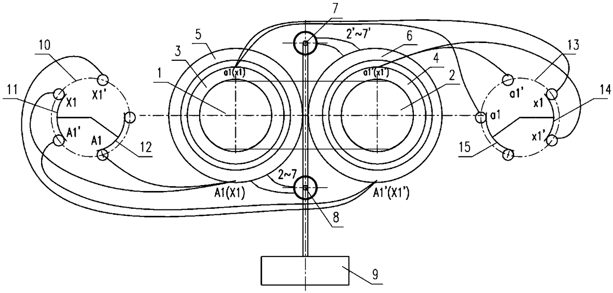
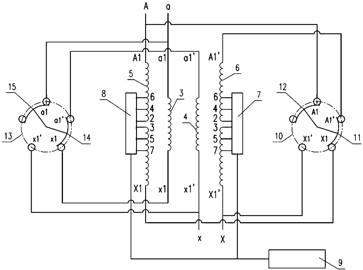
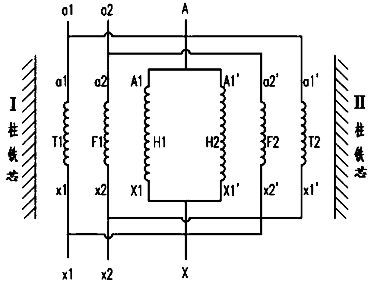
[0025] Such as Figure 1~6 As shown, a capacity regulating traction transformer includes a first iron core column 1 and a second iron core column 2, and the first iron core column 1 is provided with a first low voltage coil 3 and a first high voltage coil 5 in sequence. , the second iron core column 2 is provided with a second low voltage coil 4 and a second high voltage coil 6 outward in sequence;

[0026] The first end A1, X1 of the first high-voltage coil 5 of the first iron core column 1 and the first end A1', X1' of the second high-voltage coil 6 on the second iron core column 2 are respectively connected to the first series-parallel switch 10; The first end a1, x1 of the first low-voltage coil 3 of the first iron core column 1 and the first ...


PUM


Abstract

The invention discloses a capacity-adjusting traction transformer, which includes a first core post and a second core post, A first low-voltage coil and a first high-voltage coil are sequentially arranged outward on the first iron core post, A second low-voltage coil and a second high-voltage coil are sequentially arranged outward on the second iron core post, The first end of the first high-voltage coil and the first end of the second high-voltage coil are respectively connected to the contacts of the first series-parallel switching switch, and the first end of the first low-voltage coil andthe first end of the second low-voltage coil are respectively connected to the contacts of the second series-parallel switching switch. According to capacity-regulating traction transformer, By changing the series-parallel connection of high and low voltage coils simultaneously to realize the switching of half-capacity and full-capacity, the electric charge of basic capacity of substation can be significantly reduced, the no-load loss of traction transformer can be significantly reduced, and the operating cost of substation can be effectively reduced.

Description

technical field [0001] The invention relates to a capacity-adjusting traction transformer, which belongs to the technical field of transformers. Background technique [0002] At present, the traction transformer is an important equipment for the traction power supply system of electrified railway. Single train transportation, etc.) is relatively small. During this period, the basic electricity fee of the transformer is usually charged according to the maximum demand, but the maximum demand in the first few years is less than half of the rated capacity of the transformer, and the transformer capacity is not effectively utilized. At the same time, the operation characteristics of the traction transformer are that the no-load operation time is relatively long, and the traction transformer is basically in the no-load operation state during the gap between trains, so the no-load loss has a greater impact on the operation cost of the traction transformer. [0003] However, the ex...

Claims


Application Information

Patent Timeline
Patent Type & Authority Applications(China)
IPC IPC(8): H01F29/04H01F27/28H01F27/24
CPCH01F29/04H01F27/24H01F27/28
Inventor 高仕斌吴志强林彬彬万洪兴高旻东周利军
Owner TAIPINGYANG POWER EQUIP GROUP CHANGZHOU
Why Eureka
Try Eureka