Metal plate stamping part transfer device

A transfer device and a technology for stamping parts, applied in the field of stamping parts equipment, can solve problems such as low operation efficiency, and achieve the effect of improving work efficiency and ensuring quality

Inactive Publication Date: 2019-01-22
王玉环
View PDF6 Cites 0 Cited by
  • Summary
  • Abstract
  • Description
  • Claims
  • Application Information

AI Technical Summary

Problems solved by technology

Existing racks are generally provided with a number of cavities for placing workpieces on it to place the workpieces

Method used


Image

  • Metal plate stamping part transfer device
  • Metal plate stamping part transfer device
  • Metal plate stamping part transfer device

Examples


Embodiment Construction

[0020] The following will clearly and completely describe the technical solutions in the embodiments of the present invention with reference to the accompanying drawings in the embodiments of the present invention. Obviously, the described embodiments are only some, not all, embodiments of the present invention. Based on the embodiments of the present invention, all other embodiments obtained by persons of ordinary skill in the art without creative efforts fall within the protection scope of the present invention.

[0021] Refer as follows Figure 1-4 The present invention is described:

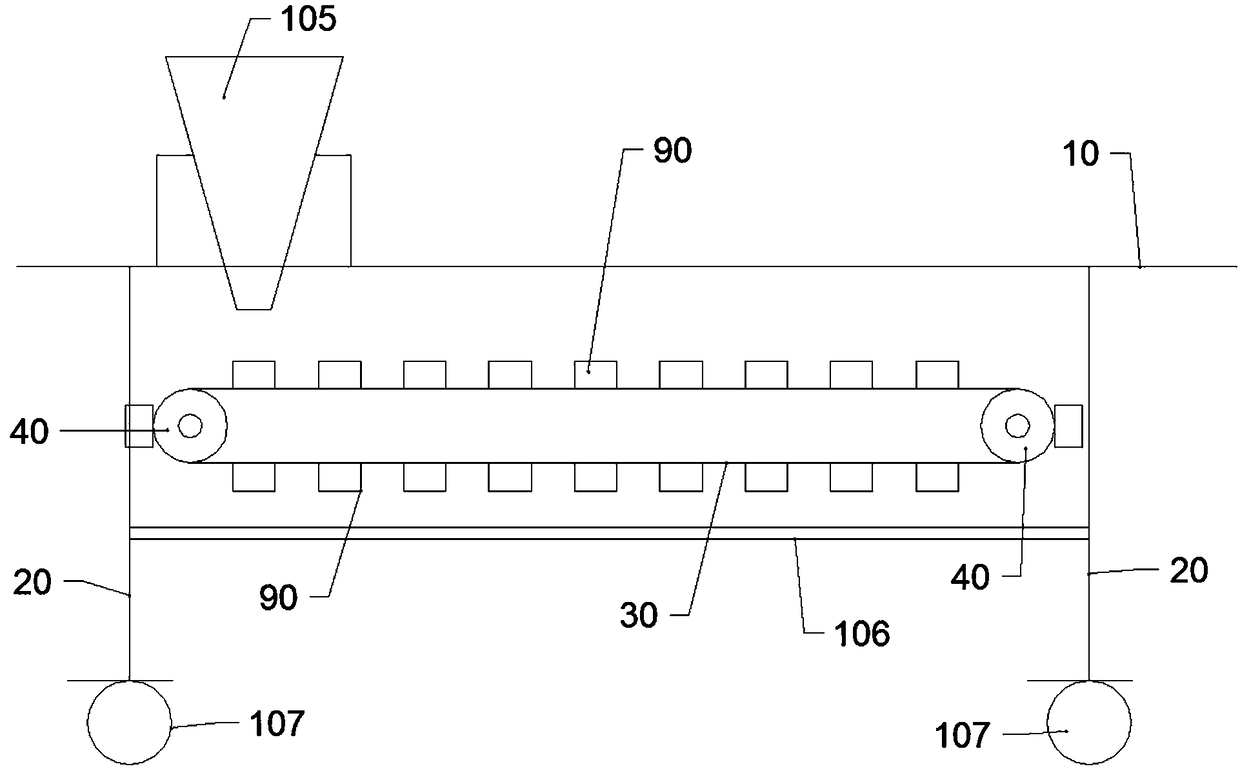
[0022] A transfer device for sheet metal stamping parts includes a frame body, and the frame body includes an upper frame body 10 and four lower legs 20 .

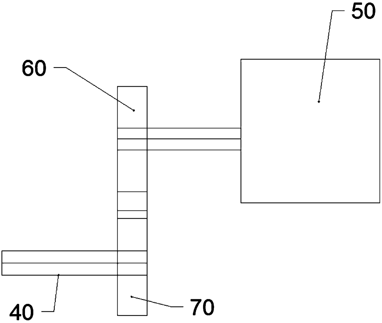
[0023] Also includes conveying device, described conveying device comprises conveying belt 30 and two conveying shafts 40, described two conveying shafts 40 are respectively arranged on the two ends of described upper frame body 10, and ...


PUM


Abstract

The invention provides a metal plate stamping part transfer device. The metal plate stamping part transfer device includes a frame, a transportation device and a drive device; the frame includes an upper frame body and four lower support legs; the transportation device includes a transportation belt and two transportation shafts, the transportation shafts are arranged at the two ends of the upperframe body respectively, the transportation belt is connected with the transportation shafts, and the transportation belt is driven to move through the transportation shafts; the drive device includesa drive motor, a drive wheel and a transmission gear, the drive motor is fixed to the corresponding lower support leg, the drive wheel is in linkage with a rotation shaft of the drive motor, the transmission gear is in coaxial linkage connection with one of the transportation shafts, and fan-shaped teeth are arranged on the outer side wall of the drive wheel and mesh with the transmission gear. The metal plate stamping part transfer device can automatically conduct material collection operation, and therefore the working efficiency and quality are improved.

Description

technical field [0001] The invention relates to the technical field of stamping parts equipment, in particular to a transfer device for sheet metal stamping parts. Background technique [0002] At present, the stamping line is generally produced in a production line. The stamped sheet metal parts need to be stored in the warehouse for the next process, and bumps should be avoided during storage. Once there are bump marks, it will affect the surface painting. [0003] Generally, the stamped sheet metal is placed on the frame, and then the frame is moved to the warehouse for storage. Existing racks are generally provided with a plurality of cavities for placing workpieces on it to place the workpieces one by one in different cavities. At present, the operations are generally performed manually, and the operation efficiency is low. Contents of the invention [0004] In view of the problems pointed out in the background technology, the present invention proposes a transfer de...

Claims


Application Information

Patent Timeline
IPC IPC(8): B21D43/22
Inventor 王玉环
Owner 王玉环
Why Eureka
Try Eureka