
Anti-retrograding speed bump

A technology of speed bumps and motion strokes, which is applied in the field of anti-reverse speed bumps, and can solve problems such as poor warning effects, uneven driver quality, and lack of ability to prevent retrograde vehicles.

Inactive Publication Date: 2019-01-22
捷途智慧交通科技(徐州)有限公司
View PDF0 Cites 1 Cited by
  • Summary
  • Abstract
  • Description
  • Claims
  • Application Information

AI Technical Summary

Problems solved by technology

[0002] At present, due to the uneven quality of road traffic drivers, the imperfect marking of traditional road traffic signs and the poor warning effect, there are illegal retrograde vehicles on many one-way streets, causing unnecessary traffic to the one-way streets that do not have two-way driving conditions. congestion
[0003] Mandatory speed control facilities represented by speed bumps have been widely used in my country. At present, the main purpose of common speed bumps is to reduce vehicle speed and improve road traffic safety, but does not have the function of preventing vehicles from going backwards.

Method used


Image

  • Anti-retrograding speed bump
  • Anti-retrograding speed bump

Examples


Embodiment Construction

[0018] The present invention will be further described below in conjunction with accompanying drawing.

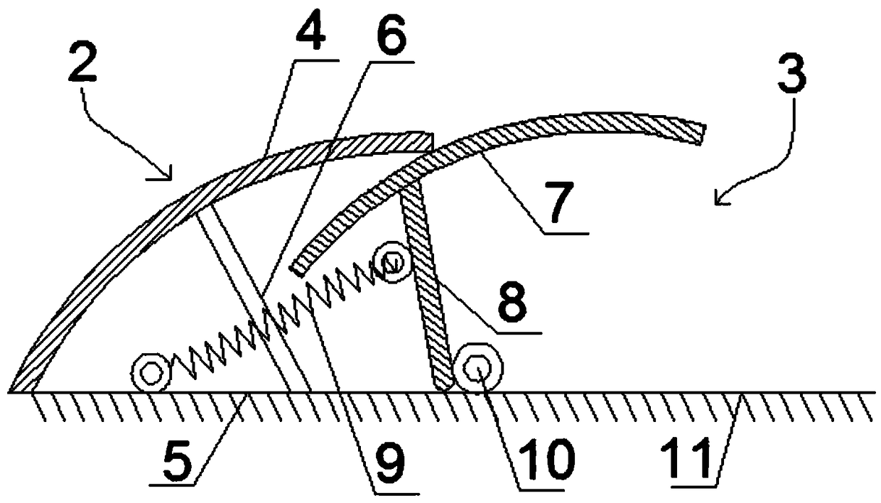
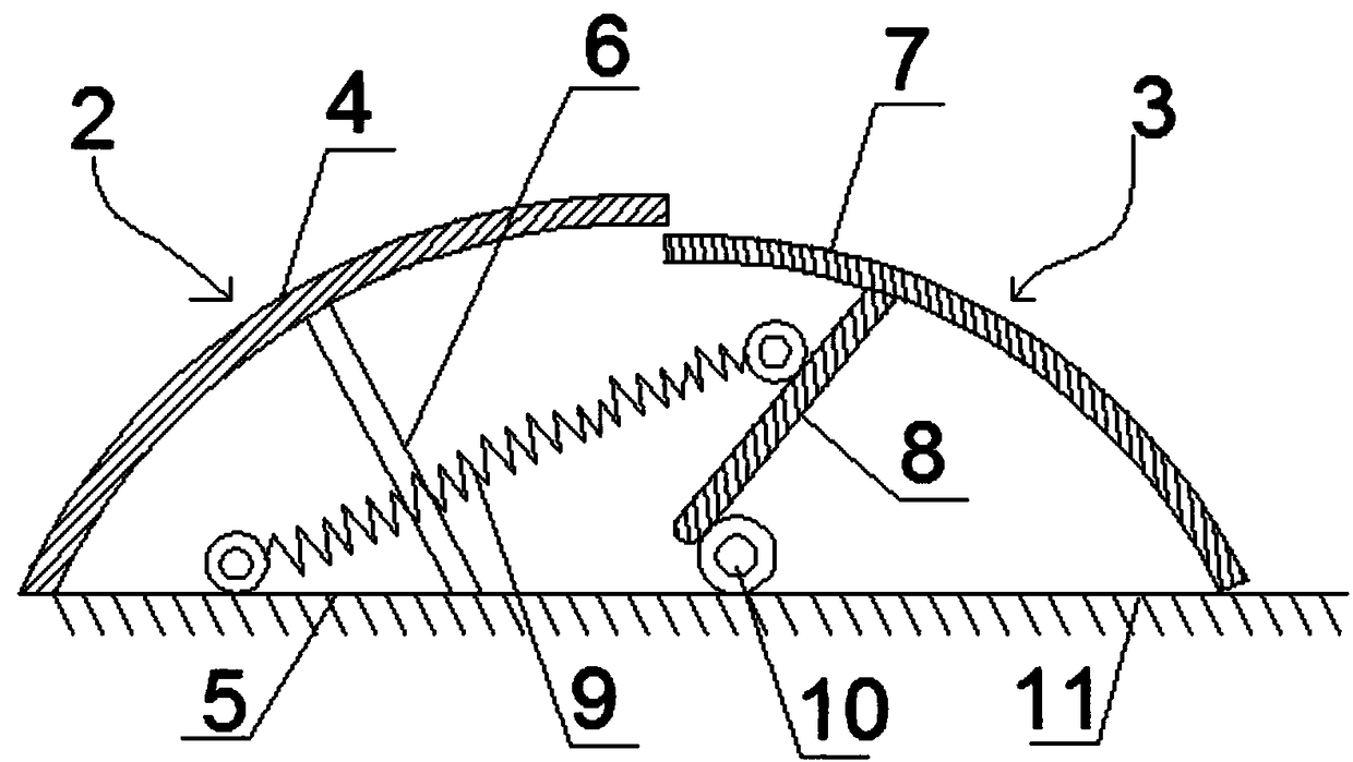
[0019] Such as figure 1 As shown, an anti-reverse deceleration belt includes a strip-shaped deceleration belt body, and the deceleration belt body includes a left deceleration belt

[0020] Speed ​​belt unit 2 and right speed belt unit 3;

[0021] The left deceleration belt unit 2 includes a top plate 4 and a bottom plate 5, wherein the top plate 4 is in the shape of a semicircle, and its left end is fixedly connected to the left end of the bottom plate 5, and a support inclined from the upper left to the lower right is provided between the top plate 4 and the bottom plate 5 block 6;

[0022] The right deceleration belt unit 3 includes an anti-reverse steel sheet 7, the lower end of the anti-reverse steel sheet 7 is connected to a rotating bracket 8, the left end of the rotating bracket 8 is connected to a tension spring 9, and the other end of the tension spring 9 is fix...


PUM


Abstract

Provided is an anti-retrograding speed bump. A left speed bump unit comprises a top plate and a bottom plate, wherein that top plate is semi-arc shaped, the left end of the top plate is fixedly connected with the left end of the bottom plate, and a support block inclined from the upper left to the lower right is arranged between the top plate and the bottom plate. A right speed bump unit comprisesan anti-retrograde steel sheet, a lower end of the anti-retrograde steel sheet is connected with a rotating bracket, a left end of the rotating bracket is connected with a tension spring, the other end of the tension spring is fixed on the bottom plate inside the left speed bump unit, and the right end of the rotating bracket is fixedly connected with a rotating shaft arranged along the length direction of the speed bump body. The anti-retrograde steel sheet is semi-arc shaped, and its left end extends into the top plate of the left speed bump unit. The right end of the anti-retrograde steelsheet is higher than the height of the right end of the top plate in the left speed bump unit. The stretching stroke of the tension spring shall not be less than the movement stroke of the right-handspeed bump unit bottom plate of the anti-retrograde steel sheet, which prevents retrograde traffic on a one-way lane and reduces traffic congestion.

Description

technical field [0001] The invention relates to a speed bump, in particular to an anti-reverse speed bump. Background technique [0002] At present, due to the uneven quality of road traffic drivers, the imperfect marking of traditional road traffic signs and the poor warning effect, there are illegal retrograde vehicles on many one-way streets, causing unnecessary traffic to the one-way streets that do not have two-way driving conditions. congestion. [0003] Mandatory speed control facilities represented by speed bumps have been widely used in my country. At present, the main purpose of common speed bumps is to reduce vehicle speed and improve road traffic safety, but does not have the function of preventing vehicles from going backwards. Contents of the invention [0004] Aiming at the above-mentioned problems in the prior art, the present invention provides an anti-reverse speed bump, which can effectively prevent the phenomenon of retrograde vehicles on a one-way str...

Claims


Application Information

Patent Timeline
IPC IPC(8): E01F9/529
CPCE01F9/529
Inventor 董琪
Owner 捷途智慧交通科技(徐州)有限公司
Learn More