Knee joint support
A knee joint and cylinder technology is applied in the field of knee joint brackets, which can solve the problems of difficult to find, inconvenient to clean, difficult to find items whose height and angle are suitable for the patient's body position, etc., and achieve the effect of stable and firm support and easy washing.
- Summary
- Abstract
- Description
- Claims
- Application Information
AI Technical Summary
Problems solved by technology
Method used
Image

Examples
Embodiment 1
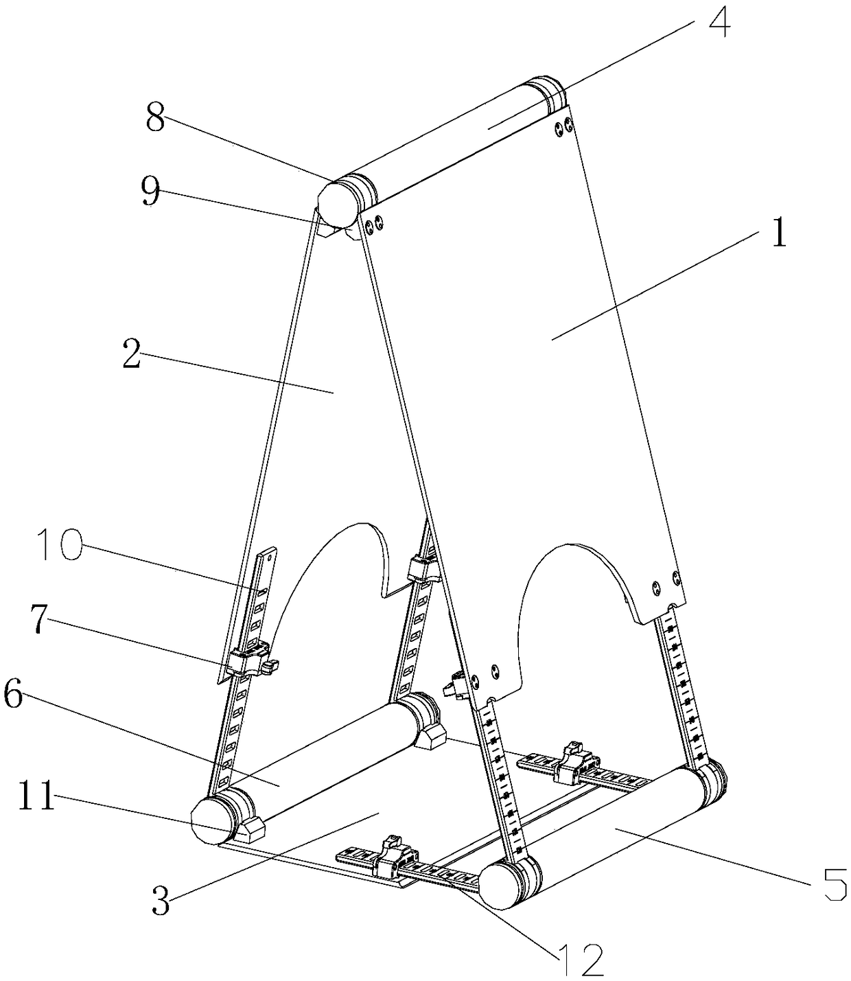
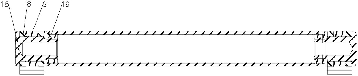
[0017] The knee joint bracket provided by the present invention is a triangular structure, including a first side plate 1, a second side plate 2 and a bottom plate 3, the first side plate 1 and the second side plate 2 are used to support the knee joint, and the first side plate 1 The upper end of the second side plate 2 is connected with the upper cylinder 4, and the upper cylinder 4 is provided with a first convex hinge 9, and the first convex hinge 9 and the concave hinge 8 are fixed by fixing bolts 18 and fixing nuts 19 At the end, the first side plate 1 and the second side plate 2 are provided with bolt holes, and the bolts on the first side plate 1 and the second side plate 2 and the first convex hinge 9 and the concave hinge 8 are connected by bolts. hole for a fixed connection. The lower end of the first side plate 1 and the second side plate 2 is provided with a lock seat 7, and the lock seat 7 is respectively fixed on the first side plate 1 and the second side plate 2...
Embodiment 2
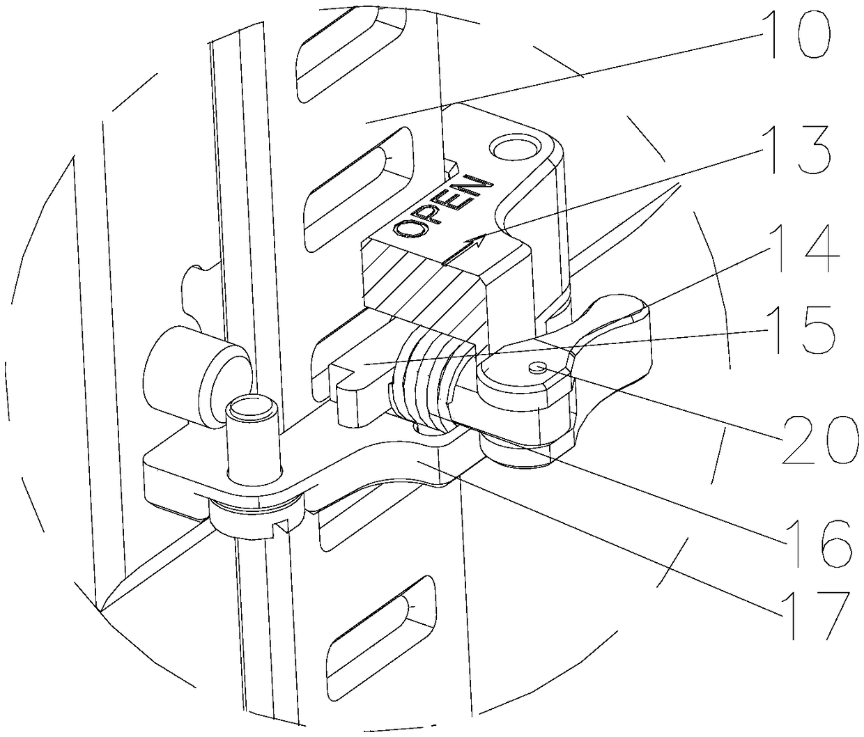
[0022] When needing to carry out knee joint operation, at first rotation rotating plate 14 controls block 15 to leave the through hole of sliding concave hinge 10, the present invention is adjusted to as figure 1 As shown, the patient's calf and thigh are placed on the first side board 1 and the second side board 2 respectively, so that the knee joint is located above the upper cylinder 4, and the height and angle are adjusted according to the needs of the operation position. The height adjustment is done by Adjust the positions of the lock seats 7 on the first side plate 1 and the second side plate 2 on the sliding concave hinges 10 connected to them, and adjust the angle by adjusting the lock seats 7 of the bottom plate 3 on the sliding concave hinges connected to them. Position on 10, after adjusting, turn rotating plate 14 and control block 15 to enter the through hole of sliding concave hinge 10 and can finish fixing, just can carry out knee joint operation after being fix...
Embodiment 3
[0024] When needing to carry out suturing operation, at first rotate rotating plate 14 and control block 15 to leave the through hole of sliding concave hinge 10, the present invention is adjusted to such as Figure 4 As shown, the patient's thigh is placed on the base plate 3, and the calf is placed on the second side plate 2, so that the knee joint is located above the second lower cylinder 6, and the height and angle are adjusted according to the needs of the operation. The height is adjusted by adjusting the second side plate. The position of the lock seat 7 of the two side plates 2 on the sliding concave hinge 10 connected to it and the position of the lock seat 7 of the bottom plate on the sliding concave hinge 10 connected to it, the angle adjustment is by adjusting the position on the first side plate 1 After adjusting the position of the lock seat 7 on the sliding concave hinge 10 connected with it, turn the rotary plate 14 to control the stopper 15 to enter the throug...
PUM
 Abstract
Description
Claims
Application Information
 - R&D
- Intellectual Property
- Life Sciences
- Materials
- Tech Scout
- Unparalleled Data Quality
- Higher Quality Content
- 60% Fewer Hallucinations
Browse by: Latest US Patents, China's latest patents, Technical Efficacy Thesaurus, Application Domain, Technology Topic, Popular Technical Reports.
© 2025 PatSnap. All rights reserved.Legal|Privacy policy|Modern Slavery Act Transparency Statement|Sitemap|About US| Contact US: help@patsnap.com