Robot spraying workstation

A technology of robots and workstations, applied in the direction of spraying devices, etc., can solve the problems of spraying dead angles, low spraying efficiency, and relatively high requirements for robot rotation freedom, and achieve the effect of saving factory land and clean workstations

Pending Publication Date: 2019-01-25
成都环龙智能机器人有限公司
View PDF0 Cites 0 Cited by
  • Summary
  • Abstract
  • Description
  • Claims
  • Application Information

AI Technical Summary

Problems solved by technology

However, the three-claw fixed discs used by existing vehicles for such large workpieces (up to 20 tons and 6 meters in diameter) are very large, which blocks a large part of the rotor area and makes the spraying effici

Method used


Image

  • Robot spraying workstation
  • Robot spraying workstation
  • Robot spraying workstation

Examples


Embodiment Construction

[0028] The following will clearly and completely describe the technical solutions in the embodiments of the present invention with reference to the accompanying drawings in the embodiments of the present invention. Obviously, the described embodiments are only some, not all, embodiments of the present invention.

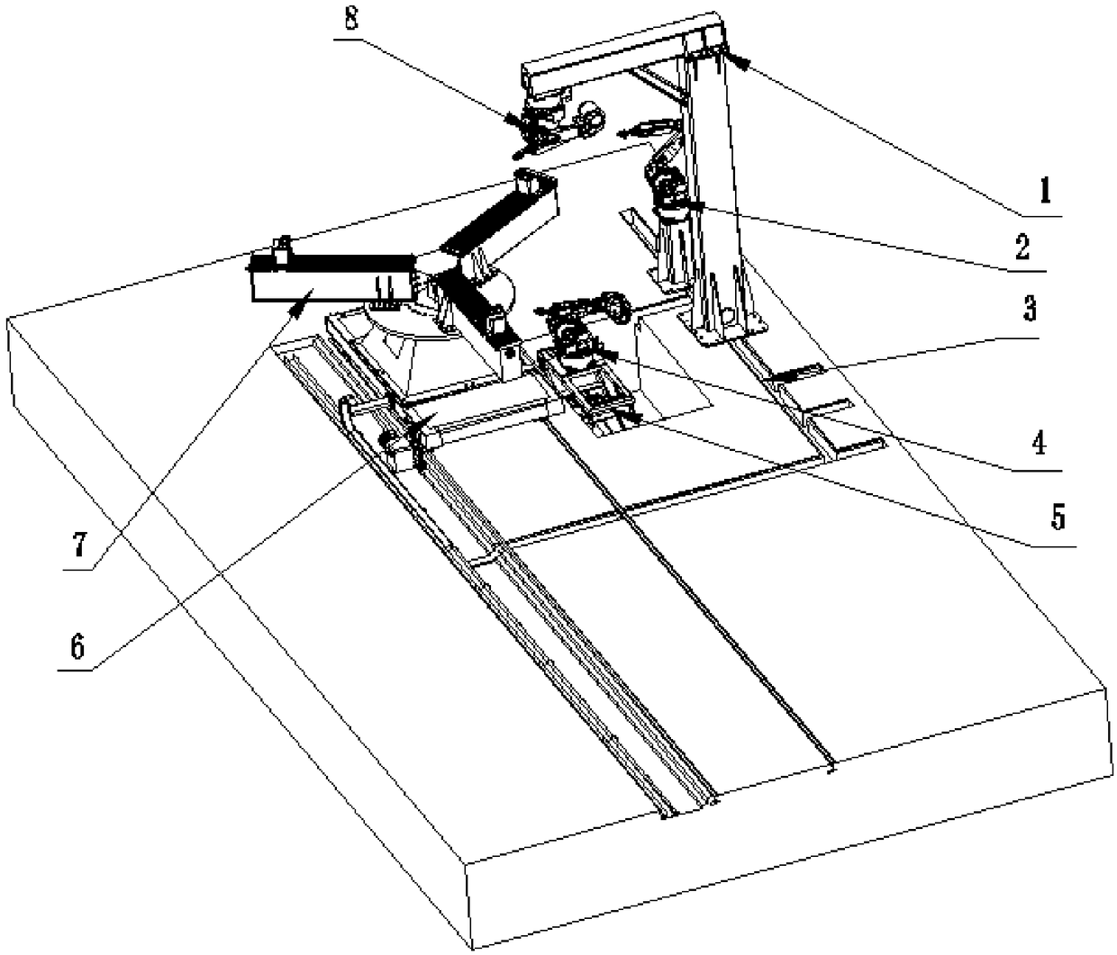
[0029] refer to figure 1 , robot spraying workstation, including the base and the bracket installed on the base 1, the side spraying robot 2, the embedding groove 3, the inner wall spraying robot 4, the lifting platform 5, the running trolley 6, the self-centering three-jaw positioning device 7 and the top The spraying robot 8, the top spraying robot 8 is installed on the support 1, and the side spraying robot 2 is located on one side of the support 1;

[0030] The embedding groove 3 is opened on the top of the base, and the embedding groove 3 is located between the support 1 and the running trolley 6, the inner wall spraying robot 4 is fixedly installed on the top o...


PUM


Abstract

The invention discloses a robot spraying workstation. The workstation comprises a base and a bracket, a side spraying robot, a buried channel, an inner wall painting robot, a lifting platform, a running trolley, a self-centering three-jaw positioning device and a top spraying robot which are mounted on the base. The top spraying robot is mounted on the bracket, and the side spraying robot is located on one side of the bracket. The buried channel is opened in the top of the base, and located between the bracket and the running trolley. The inner wall spraying robot is fixedly mounted on the topof the lifting platform, and the self-centering three-jaw positioning device is mounted on the top of the running trolley. The workstation adopts similar concealed wiring, thereby being tidier and avoiding accidents like wire intertwining on the platform during operation. The side spraying robot is arranged beside the bracket, and robot arms can be stored to create conditions for compact design of the workstation, and the factory land is saved.

Description

technical field [0001] The invention relates to the technical field of workpiece spraying, in particular to a robot spraying workstation. Background technique [0002] In the spraying process of workpieces, it is a relatively mature technology to use robots instead of manual operations. From the simple spraying of a single robot to the robotic spraying workstation composed of multiple robots, they have appeared in many actual industrial application scenarios. And for different use environments and different workpiece shapes, the design of the robot workstation is also diverse. Specifically, for the spraying process of large or super-large rotors, the existing technology can also do it, and the spraying on the top, side, and interior of the rotor can be satisfied. Considering that the rotor needs to be transported before spraying, the spraying needs to be completed in time. Therefore, the usual idea is to let the spraying work be completed directly on the carrier, and then d...

Claims


Application Information

Patent Timeline
IPC IPC(8): B05B13/06
CPCB05B13/0627B05B13/0645
Inventor 敬建雄
Owner 成都环龙智能机器人有限公司
Why Eureka
Try Eureka