Novel cross grid cluster equipment

A horizontal grid, a new type of technology, applied in the direction of metal processing, etc., can solve the problems of cumbersome operation, large cutting size error, single function, etc., and achieve the effect of simple and efficient replacement operation

Inactive Publication Date: 2019-01-25
广州建德农业科技有限公司
View PDF0 Cites 0 Cited by
  • Summary
  • Abstract
  • Description
  • Claims
  • Application Information

AI Technical Summary

Problems solved by technology

[0002] When producing tufts, it is necessary to cut and process the horizontal grid on the cluster. The current cutting equipment usually only has a one-way cutting function, and its function is single. During the cutting process, the direction of the horizontal grid needs to be adjusted manually, and the operation is cumbersome. , the work efficiency is low, and the cutting process of the horizontal grid requires manual control operation, the cutting size error is large, and the replacement steps of the cutting sheet are cumbersome, so it needs to be improved

Method used


Image

  • Novel cross grid cluster equipment
  • Novel cross grid cluster equipment
  • Novel cross grid cluster equipment

Examples


Embodiment Construction

[0016] Combine below Figure 1-4 The present invention will be described in detail.

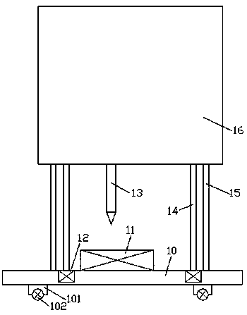
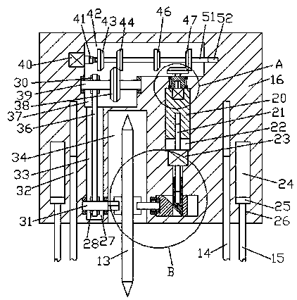
[0017] refer to Figure 1-4 , according to an embodiment of the present invention, a new type of horizontal grid cluster equipment includes a main frame body 16 and a lifting adjustment mechanism arranged on the lower side of the main frame body 16, and an installation cavity is provided in the bottom end surface of the main frame body 16 34. The installation cavity 34 is provided with a cutting piece 13, and the left and right sides of the cutting piece 13 are fixed with convex blocks 71 symmetrically in the center, and the left side of the left side of the convex block 71 is provided with a first flower. The key cavity 75, the right side of the right side of the protrusion 71 is provided with an insertion cavity 76, the first transmission cavity 33 is extended up and down in the main frame body 16 on the left side of the installation cavity 34, and the first transmission cavity 33 is arran...


PUM


Abstract

The invention discloses novel cross grid cluster equipment. The novel cross grid cluster equipment comprises a main frame body and a lifting adjusting mechanism arranged on the lower side of the mainframe body. A mounting cavity is formed in the bottom end face of the main frame body, a cutting piece is arranged in the mounting cavity, convex blocks are symmetrically fixedly arranged in the centers of the left end face and the right end face of the cutting piece, a first spline cavity is formed in the left end face of the convex block on the left side, an inserting cavity is formed in the right end face of the convex block on the right side, a first transmission cavity vertically stretches to the portion, on the left side of the mounting cavity, in the main frame body, a first rotary shaft is mounted on the lower side of the first transmission cavity in rotary fit, a first belt wheel is fixedly arranged on the outer surface of the first rotary shaft, the tail end of the right side ofthe first rotary shaft stretches into the mounting cavity, a first spline shaft is fixedly arranged at the tail end of the right side of the first rotary shaft, the first spline shaft and the first spline cavity are in spline fit connection, and the top wall of the first transmission cavity is communicated with a second transmission cavity.

Description

technical field [0001] The invention relates to the technical field of cluster tool processing, in particular to a novel horizontal grid cluster device. Background technique [0002] When producing tufts, it is necessary to cut and process the horizontal grid on the cluster. The current cutting equipment usually only has a one-way cutting function, and its function is single. During the cutting process, the direction of the horizontal grid needs to be adjusted manually, and the operation is cumbersome. , the work efficiency is low, and the cutting process of the horizontal grid requires manual control operation, the cutting size error is large, and the replacement steps of the cutting sheet are cumbersome, so it needs to be improved. Contents of the invention [0003] The object of the present invention is to provide a novel horizontal grid cluster device for overcoming the above-mentioned defects in the prior art. [0004] A new type of horizontal grid cluster equipment ...

Claims


Application Information

Patent Timeline
Patent Type & Authority Applications(China)
IPC IPC(8): B26D1/28B26D7/02B26D7/26
CPCB26D1/28B26D7/02B26D7/26
Inventor 陈杨珑
Owner 广州建德农业科技有限公司
Why Eureka
Try Eureka