Full-automatic wire-mounted binding machine and wire binding method

A fully automatic, binding machine technology, applied in binding and other directions, can solve problems such as troublesome binding, unstable threading process, low binding efficiency, etc., to achieve fast binding speed, stable and reliable threading process and knotting process, and high binding efficiency. Effect

Active Publication Date: 2019-01-25
东莞市微力机电有限公司
View PDF7 Cites 12 Cited by
  • Summary
  • Abstract
  • Description
  • Claims
  • Application Information

AI Technical Summary

Problems solved by technology

Manual binding is very troublesome, time-consuming and labor-intensive
[0003] In the prior art, there is a wire-bound binding machine capable of automatic drilling and automatic threading, as shown in the Chinese invention patent with the Chinese patent number ZL201511031596.2 and the patent name "wire-type full intelligent binding machine". However, it exists The following disadvantages: 1. The drilling and binding speed is very slow, and the binding efficiency is very low; 2. The threading process is unstable, and it is easy to drop or hook the thread; 3. It is easy to break the thread, especially during the threading process and file movement. ; 4. There is no automatic knotting, and finally the user needs to automatically tie the knot manually

Method used


Image

  • Full-automatic wire-mounted binding machine and wire binding method
  • Full-automatic wire-mounted binding machine and wire binding method
  • Full-automatic wire-mounted binding machine and wire binding method

Examples


Embodiment Construction

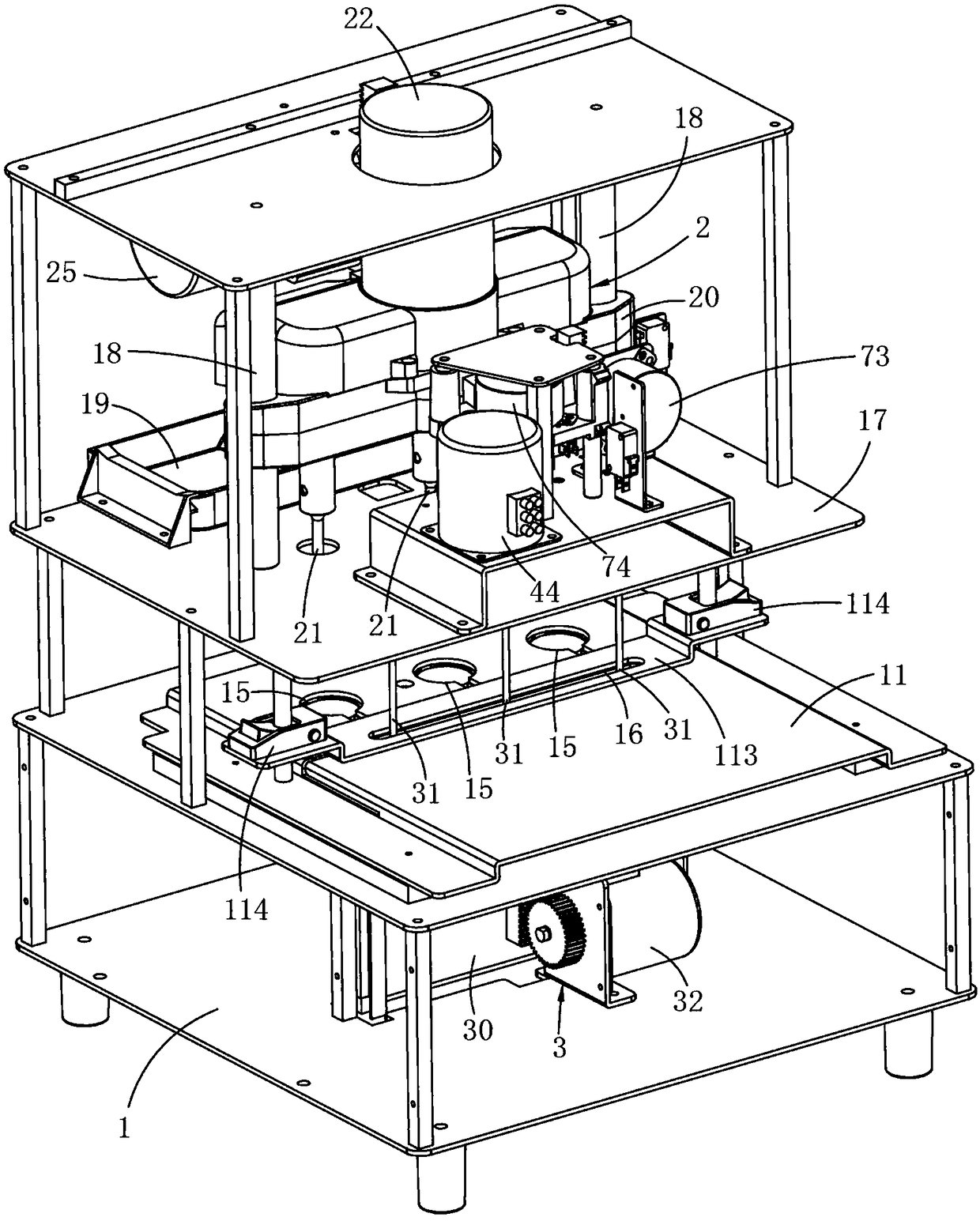
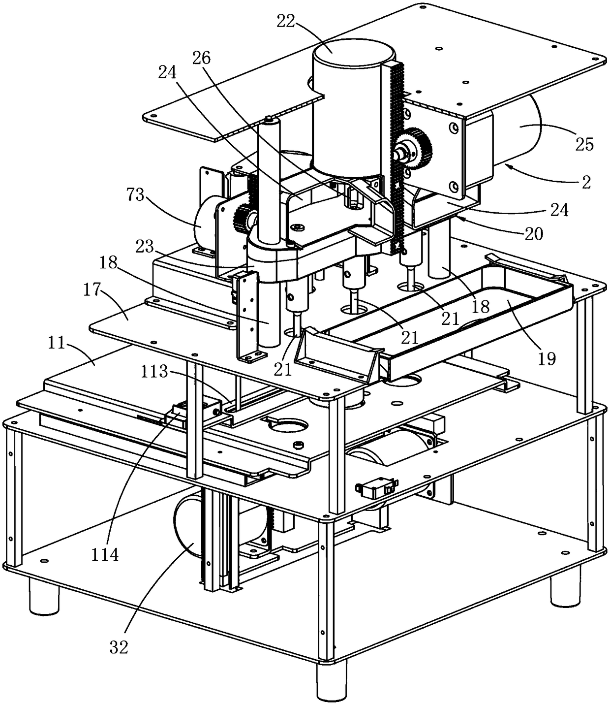
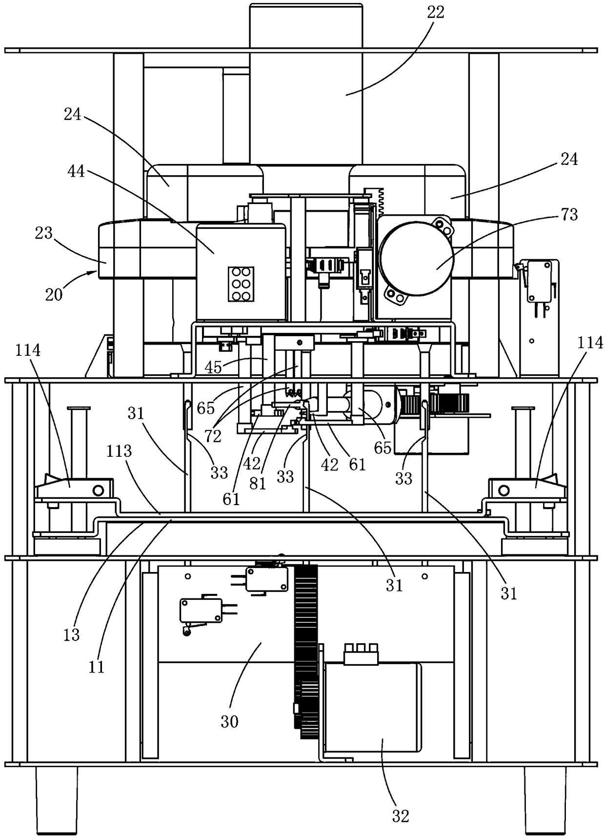
[0041] A fully automatic thread-bound binding machine, Figures 1 to 15 As shown, including a frame 1, a bottom plate 13 is fixed in the middle of the frame 1, and a binding platform 11 is slidably installed in the middle of the frame 1 for placing documents to be bound. Specifically, a platform driving motor 110 is fixed on the bottom plate 13, The bottom surface of the binding platform 11 is fixed with a platform driving rack 111 , and the platform driving motor 110 is connected to the platform driving rack 111 to drive the binding platform 11 to slide back and forth.

[0042] The left and right sides of the binding platform 11 are respectively fixed with a paper-pressing guide column 112, and the top of the binding platform 11 is provided with a paper-pressing plate 113, and the left and right sides of the paper-pressing plate 113 are slidably installed on the paper-pressing guide column 112 of the left and right sides respectively, and the paper-pressing plate Both sides o...


PUM


Abstract

The invention discloses a full-automatic wire-mounted binding machine and a wire binding method. The machine comprises a frame, a binding platform for placing a document to be bound is slidably installed in the middle of the frame, a drilling device is installed above the binding platform, and the drilling device is horizontally provided with at least two drill knives arranged at intervals for drilling a threading hole in the document to be bound; an automatic tying device is installed above the binding platform, and the automatic tying device is disposed on one side of the drilling device; athreading groove is formed under the binding platform; a threading mechanism is installed under the binding platform; the threading mechanism is provided with at least two threading pins laterally spaced apart, and each threading pin is respectively disposed directly below the threading groove; the binding platform is provided with at least one hollow area for the drill knife or the threading pinto pass. The machine automatically drills and automatically knots, and achieves automatic wire binding.

Description

technical field [0001] The invention relates to the technical field of wire-bound binding machines, in particular to a fully automatic wire-bound binding machine and a fully automatic wire-bound binding method. Background technique [0002] At present, most enterprises require the binding of documents and financial documents to be bound by threading. The binding process is to first drill multiple through holes in documents or financial documents, and then manually thread the binding cotton threads according to the binding requirements. Each through hole, and finally the two ends of the binding cotton thread are manually knotted to bind the documents or financial documents into a book. Manual binding is very troublesome, time-consuming and labor-intensive. [0003] In the prior art, there is a wire-bound binding machine capable of automatic drilling and automatic threading, as shown in the Chinese invention patent with the Chinese patent number ZL201511031596.2 and the paten...

Claims


Application Information

Patent Timeline
Patent Type & Authority Applications(China)
IPC IPC(8): B42B2/04B42B2/08B42B9/00
CPCB42B2/04B42B2/08B42B9/00
Inventor 曹东华廖建新
Owner 东莞市微力机电有限公司
Why Eureka
Try Eureka