Splicing display system

A splicing display and seam technology, applied in optics, instruments, projection devices, etc., can solve the problems of image segmentation and poor image display effect, and achieve the effect of eliminating image seams

Active Publication Date: 2019-01-25
GUANGDONG VTRON TECH CO LTD
View PDF19 Cites 4 Cited by
  • Summary
  • Abstract
  • Description
  • Claims
  • Application Information

AI Technical Summary

Problems solved by technology

Since there is no light to reach the splicing gap 12, a black line is formed at the splicing gap 12, resulting in the image segmentation phenomenon; When the temperature is affected, the size of the material changes regularly, that is to say, when the temperature changes, the splicing seam 12 will also change accordingly, resulting in poor image display effect

Method used


Image

  • Splicing display system
  • Splicing display system
  • Splicing display system

Examples


Embodiment Construction

[0034] The following will clearly and completely describe the technical solutions in the embodiments of the present invention with reference to the accompanying drawings in the embodiments of the present invention. Obviously, the described embodiments are only some, not all, embodiments of the present invention. Based on the embodiments of the present invention, all other embodiments obtained by persons of ordinary skill in the art without making creative efforts belong to the protection scope of the present invention.

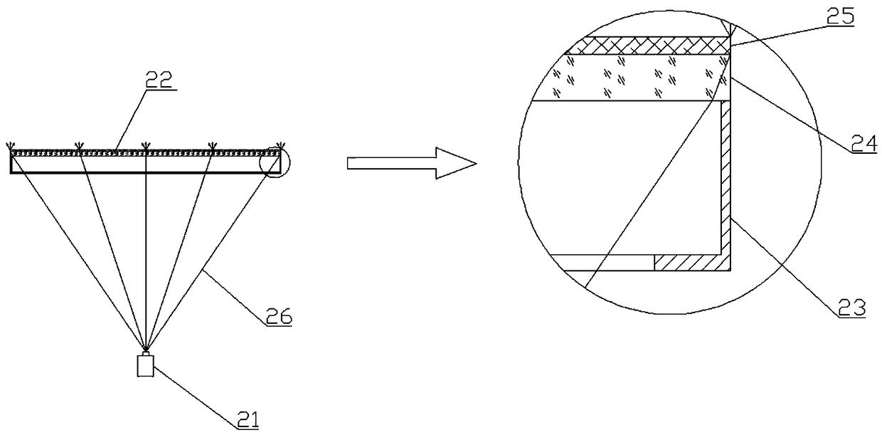
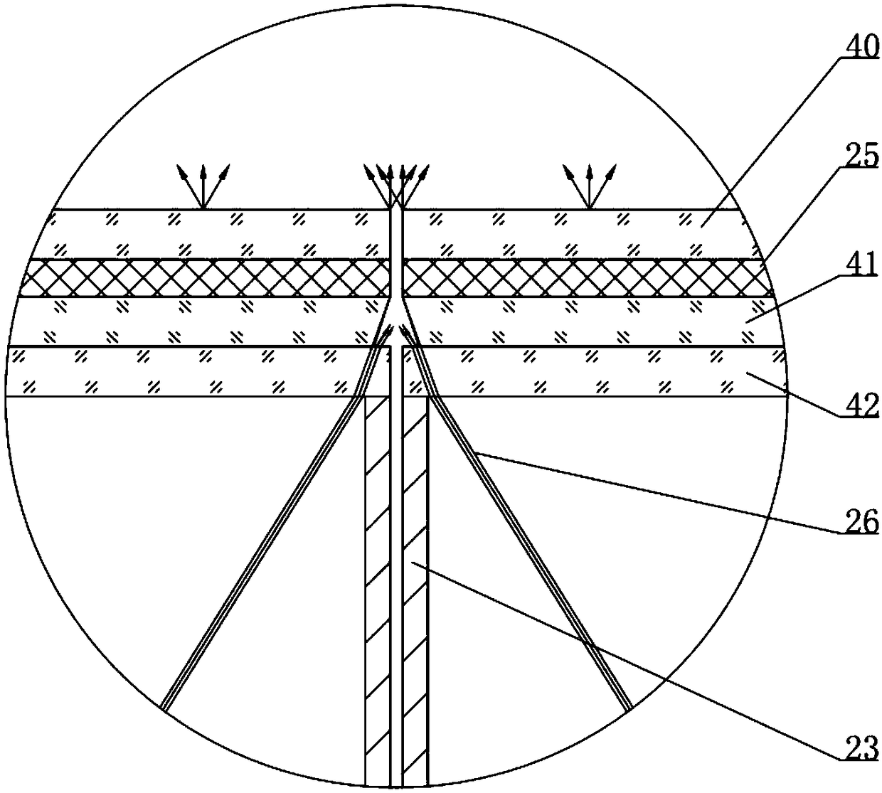
[0035] The present invention provides a splicing display system, such as image 3 As shown, it includes: a plurality of mutually spliced ​​rear projection units 11, and there is a splicing seam 12 between two adjacent rear projection units 11; each rear projection unit 11 includes a projector 21 and a screen assembly 22, and the screen assembly 22 includes a fixed The bracket 23, the Fresnel lens 41 and the rear projection screen 25 fixedly connected in sequen...


PUM


Abstract

The invention discloses a splicing display system, comprising: a plurality of mutually spliced back projection units, wherein a splicing joint exists between two adjacent back projection units; each rear projection unit comprises a projector and a screen assembly, wherein the screen assembly comprises a Fresnel lens and a rear projection screen, and two adjacent Fresnel lenses are spliced with each other; the projector projects light beyond the range of the display image of the rear projection screen and beyond a part of the light projected onto the side of the screen assembly. The side surfaces of each Fresnel lens which are spliced with each other are provided with tangent angles; also included is an adaptive adjustment device for detecting changes in ambient temperature and automatically adjusting the size of a projector projection picture according to a preset program. The range of light emitted by the projector in the application is enlarged compared with the prior art, and part of the light can enter into the splice joint through the side of the screen assembly, and then is emitted from the front of the rear projection screen, so that the splice black line is completely eliminated, and the best effect of eliminating the black line can be maintained when the temperature is changed.

Description

technical field [0001] The invention relates to the field of display technology, in particular to a splicing display system. Background technique [0002] The rear projection splicing wall is a professional display application. It adopts a modular display unit structure, which can easily and conveniently splice multiple image units together to achieve ultra-large screen and ultra-high-resolution image display. At present, although the image stitching of the existing unitized mosaic wall has been made very small, less than one pixel of the image, and there is almost no image loss, there are still obvious stitching seams between adjacent units, and the display screen is visually There are obvious black line divisions on the screen, which affects the integrity of the image, and the panoramic integrated display effect of seamless stitching technology cannot be achieved. [0003] Such as figure 1 As shown, a common splicing display system is composed of a plurality of rear proj...

Claims


Application Information

Patent Timeline
Patent Type & Authority Applications(China)
IPC IPC(8): G09F9/302G03B21/14G03B21/56
CPCG03B21/142G03B21/56G09F9/3026
Inventor 罗振华
Owner GUANGDONG VTRON TECH CO LTD
Why Eureka
Try Eureka