Camera module control method, control device and mobile terminal

A technology of a camera module and a control method, which is applied in image communication, color TV parts, TV system parts, etc., and can solve problems such as lack of detection devices, power consumption, and waste of energy

Pending Publication Date: 2019-01-25
GREE ELECTRIC APPLIANCES INC
View PDF0 Cites 12 Cited by
  • Summary
  • Abstract
  • Description
  • Claims
  • Application Information

AI Technical Summary

Problems solved by technology

[0003] The use of full-screen mobile terminals has become a popular trend. The full-screen can increase the screen-to-body ratio of mobile terminals and achieve a large field of view on a limited screen. However, most of the mobile terminals with shooting functions are now on mobile terminals Holes are opened on the surface of the head or bottom cover, and the traditional camera is installed in the hole to achieve shooting. The position of the front camera and the hole restricts the design of the full screen, which always leaves a large or small "forehead", which is very difficult. Affects the maximization of the full screen
[0004] Now there are some mobile terminals that can realize a full screen. The camera is installed in the rotating module, and the rotating module is rotated out to realize the shooting function. When not in use, the rotating module is screwed into the housing, and the rotating module is rotated 90° through the mobile phone system or manually. Finally, the rotating module is unscrewed from the mobile phone, the camera is started, and the Selfie function is realized. After the front camera is turned off, the rotating module is rotated to hide it in the mobile phone. The rotating module is screwed into the casing, but it faces the following disadvantages: lack of corresponding detection device, when the camera is in the screwed-in state, if the camera is turned on at this time, it cannot be easily found because it is hidden in the mobile phone, which will cause unnecessary power consumption, waste of energy

Method used


Image

  • Camera module control method, control device and mobile terminal
  • Camera module control method, control device and mobile terminal
  • Camera module control method, control device and mobile terminal

Examples


Embodiment Construction

[0098] In order to make the purpose, technical solution and advantages of the present invention clearer, the technical solution of the present invention will be described in detail below. Apparently, the described embodiments are only some of the embodiments of the present invention, but not all of them. Based on the embodiments of the present invention, all other implementations obtained by persons of ordinary skill in the art without making creative efforts fall within the protection scope of the present invention.

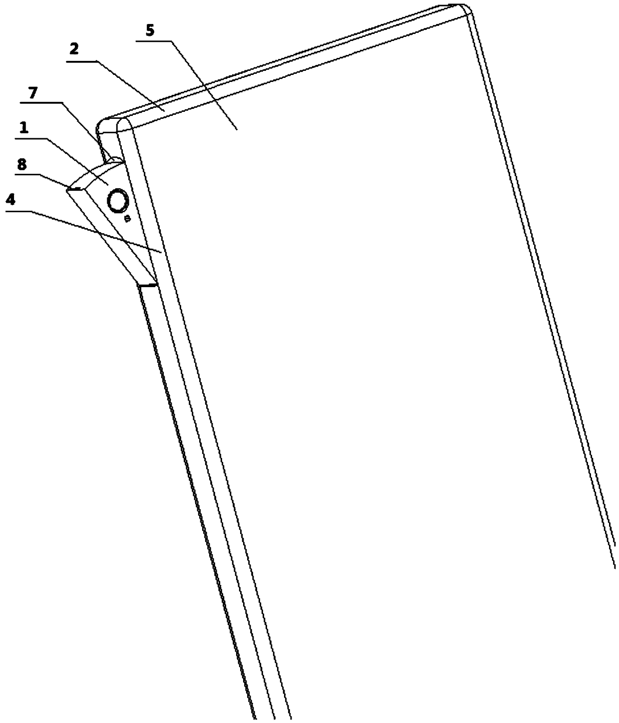
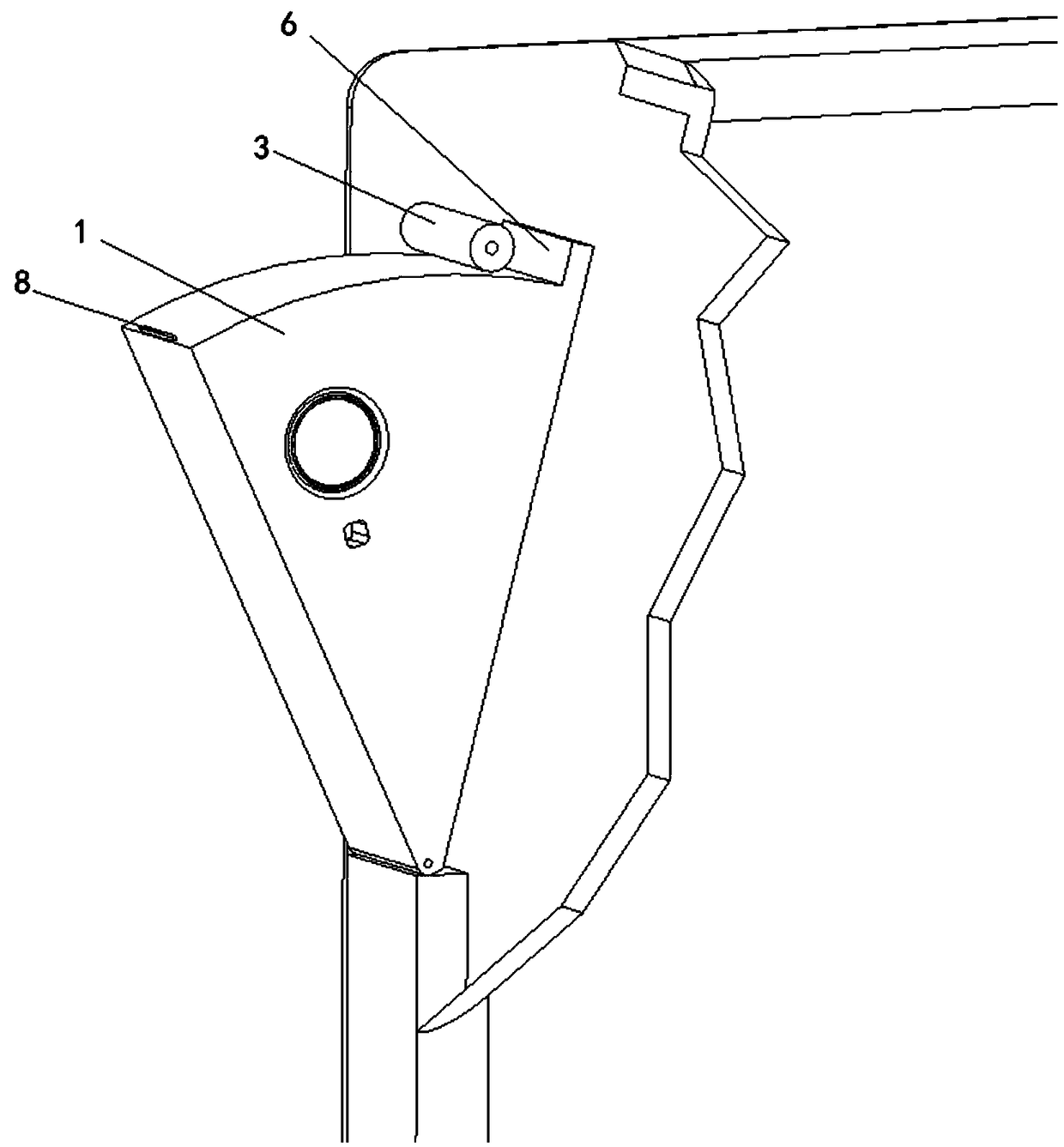
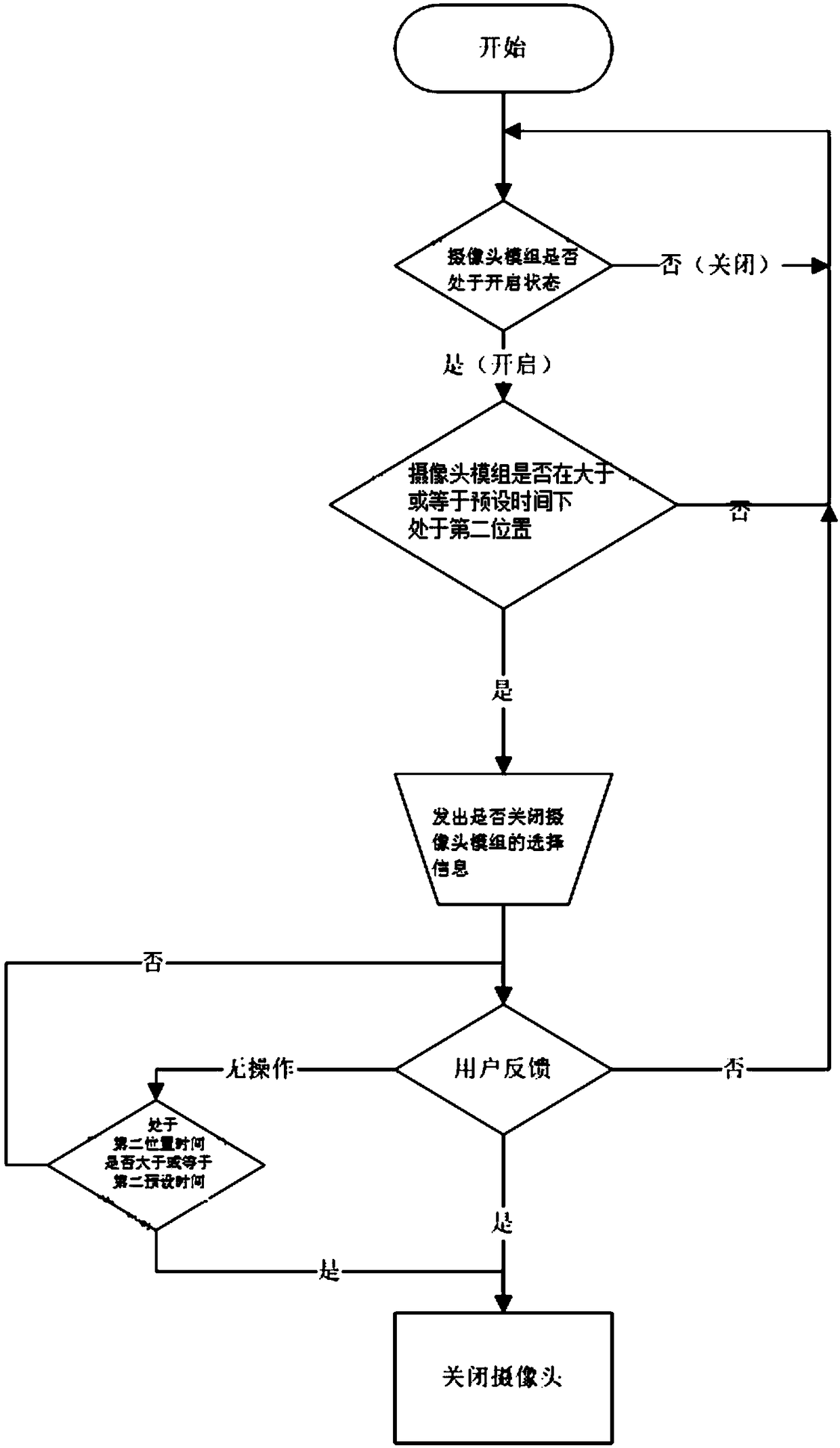
[0099] A specific embodiment of the present invention provides a method for controlling a camera module, such as Figure 1-Figure 6 As shown, the camera module 1 is arranged on the casing 2 of the mobile terminal, and the camera module 1 is movably arranged on the casing 2 of the mobile terminal. The first position for shooting and the second position that can be hidden in the casing 2, the control method includes: judging whether the camera module 1 is in the ...


PUM


Abstract

The invention provides a control method of a camera module, which relates to the technical field of terminal structure. The camera module of the invention is movably arranged on the housing of the mobile terminal, and the moving position of the camera module comprises a first position capable of exposing the housing for external photographing and a second position capable of being hidden in the housing. The control method comprises the following steps: judging whether the camera module is in the second position; and the camera module is movably arranged on the housing of the mobile terminal. If so, the camera module is turned off. The invention also provides a control device of a camera module and a mobile terminal. By adding a detection device for detecting the position of the camera module, the controller controls the camera module to be closed when the camera module is hidden in a housing, thereby saving energy and avoiding unnecessary power consumption.

Description

technical field [0001] The present invention relates to the technical field of terminal structures, in particular to a camera module control method, a control device and a mobile terminal. Background technique [0002] Mobile terminal electronic products such as smartphones and PADs (tablet computers) have been widely used in people's daily life. Mobile terminal electronic products can watch news, watch performances and have shooting functions, and are loved by people. [0003] The use of full-screen mobile terminals has become a popular trend. The full-screen can increase the screen-to-body ratio of mobile terminals and achieve a large field of view on a limited screen. However, most of the mobile terminals with shooting functions are now on mobile terminals Holes are opened on the surface of the head or bottom cover, and the traditional camera is installed in the hole to achieve shooting. The position of the front camera and the hole restricts the design of the full screen...

Claims


Application Information

Patent Timeline
Patent Type & Authority Applications(China)
IPC IPC(8): H04N5/232H04N5/225H04M1/02
CPCH04M1/0264H04N23/57H04N23/65
Inventor 许云峰杨华生张赛超
Owner GREE ELECTRIC APPLIANCES INC
Why Eureka
Try Eureka