
Under-actuated rope-drive mechanical arm

A manipulator, underactuated technology, applied in manipulators, program-controlled manipulators, manufacturing tools, etc., can solve the problems of increase of drive motors, reducers and other related parts, mechanical failure rate and cost increase, etc., to reduce the mechanical failure rate. , the structure is simple and reliable, the effect of convenient control

Inactive Publication Date: 2019-01-29
享奕自动化科技(上海)有限公司
View PDF6 Cites 13 Cited by
  • Summary
  • Abstract
  • Description
  • Claims
  • Application Information

AI Technical Summary

Problems solved by technology

[0003] The increase of wire rope will inevitably lead to the increase of drive motor, reducer and other related parts, so the mechanical failure rate and cost will increase accordingly

Method used


Image

  • Under-actuated rope-drive mechanical arm
  • Under-actuated rope-drive mechanical arm
  • Under-actuated rope-drive mechanical arm

Examples


Embodiment 1

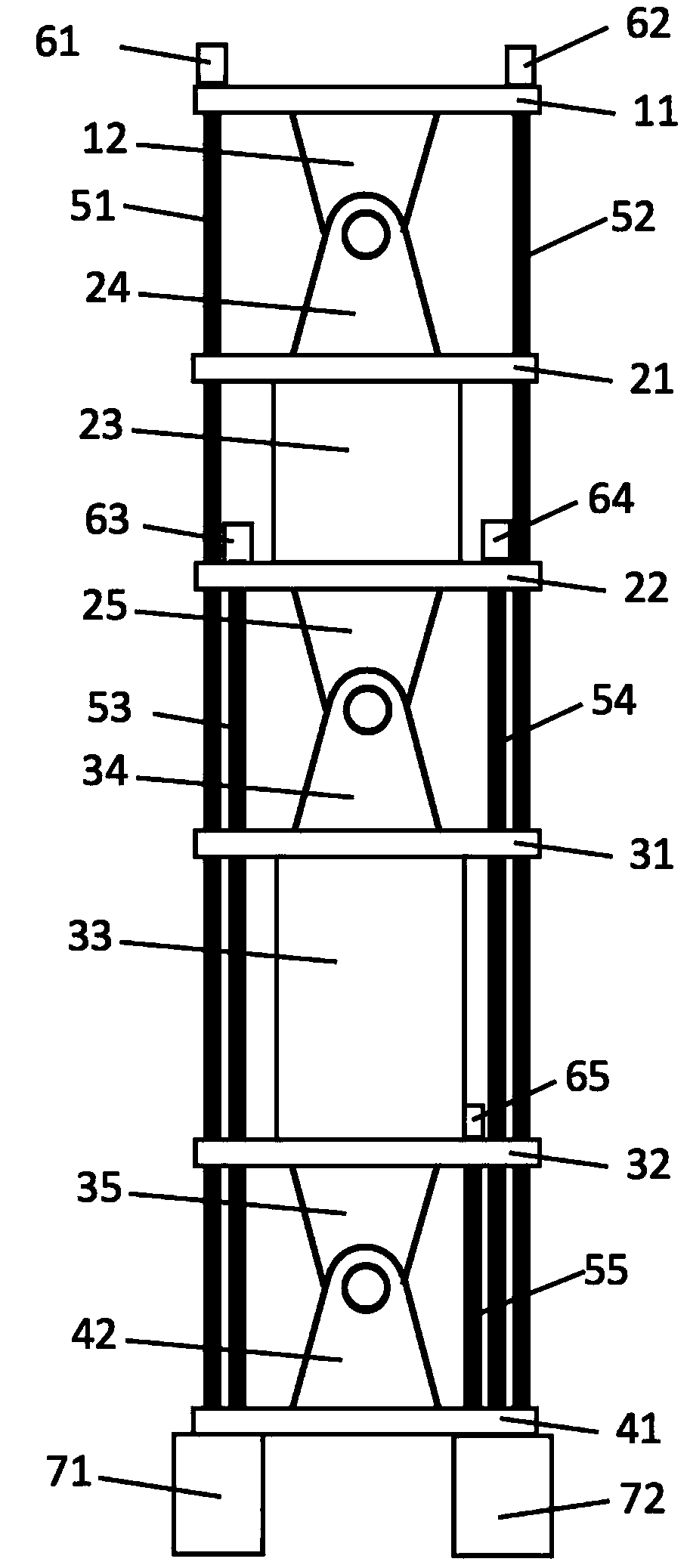
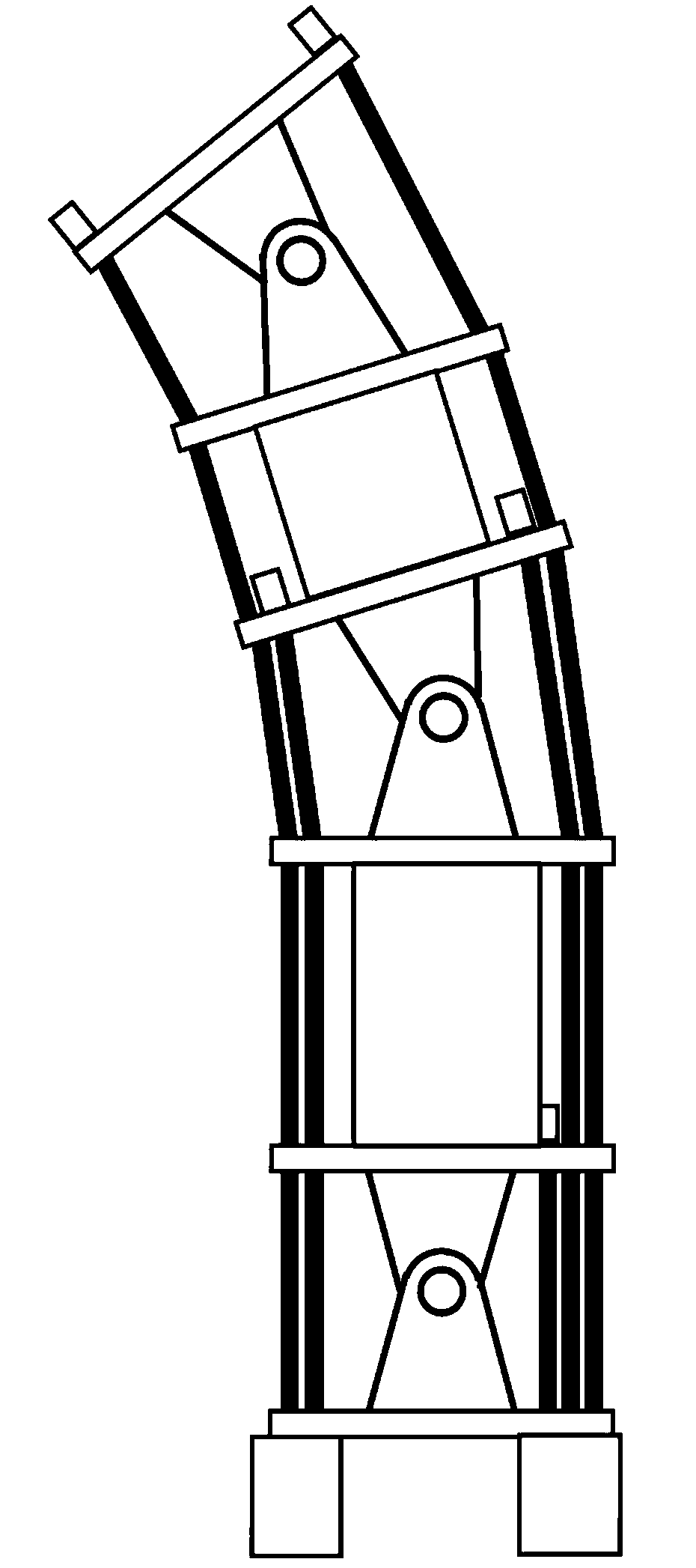
[0028] ginseng figure 1 As shown, an under-actuated rope-driven mechanical arm in this embodiment includes a plurality of rotatable joints, driving ropes connected between the joints, and several ropes for retracting and / or releasing the wires. The joint includes a first joint at the bottom, a second joint at the top, and several third joints between the first joint and the second joint. Directly or indirectly connected, at least one side of the third joint is directly or indirectly connected to the first joint through the second driving rope.

[0029] The joint in this embodiment includes several connecting plates and support frames fixedly installed on the connecting plates, and the joints are installed through the rotating support frame.

[0030] Specifically, this embodiment includes four joints, one first joint, one second joint and two third joints. The first joint includes a first connecting plate 41 and a first support frame 42, the second joint includes a second con...

Embodiment 2

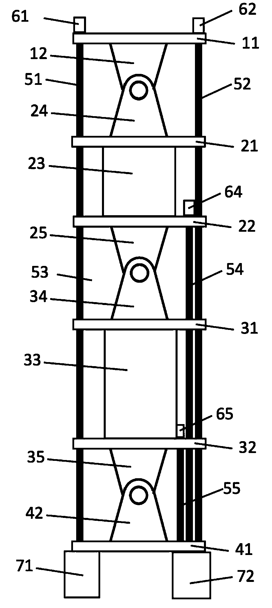
[0046] ginseng image 3 As shown, in the under-actuated rope-driven mechanical arm in this embodiment, the joint structure is exactly the same as in Embodiment 1. The difference from Embodiment 1 is that only four driving ropes are included in this embodiment. The first driving rope 51, 52. The arrangement of the second driving rope 54 and the second driving rope 55 is exactly the same as that in Embodiment 1, and the second driving rope 53 and the corresponding head sealer 63 in Embodiment 1 are not provided in this embodiment.

[0047] to combine Figure 4 As shown, the control principle of the rope-driven mechanical arm in this embodiment is as follows:

[0048] The counterclockwise rotation of the second joint, the upper third joint, and the lower third joint is all realized by pulling the first drive rope 51 through the rope retractor 71. When the rope retractor 71 pulls the first drive rope 51, the rope retracts and retracts. The device 72 releases the first driving ro...


PUM


Abstract

The invention discloses an under-actuated rope-drive mechanical arm which comprises a plurality of rotatable joints, driving ropes and a plurality of rope retracting-releasing devices, wherein the driving ropes are connected among the joints; the rope retracting-releasing devices are used for rope retracting and / or releasing; the joints comprise a first joint, a second joint and a plurality of third joints; the first joint is positioned at the bottom; the second joint is positioned at the top; the third joints are positioned between the first joint and the second joint; two sides of the secondjoint are directly or indirectly connected with the first joint through first driving ropes; and at least one side of each third joint is directly or indirectly connected with the first joint throughsecond driving ropes. The under-actuated rope-drive mechanical arm has the beneficial effects that the structure is simple and reliable; the control is convenient; the quantity of the driving ropes is reduced; the mechanical failure rate is lowered; and the mechanical arm manufacturing cost is reduced.

Description

technical field [0001] The invention relates to the technical field of a rope-driven mechanical arm, in particular to an underactuated rope-driven mechanical arm. Background technique [0002] In the prior art, each joint of the rope-driven manipulator needs to be driven by at least two wire ropes, two wire ropes are required for a joint with one degree of freedom, and three or four wire ropes are required for a joint with two degrees of freedom. [0003] The increase of wire ropes will inevitably lead to the increase of drive motors, reducers and other related parts, so the mechanical failure rate and cost will also increase accordingly. [0004] Therefore, in view of the above technical problems, it is necessary to provide an underactuated rope-driven mechanical arm. Contents of the invention [0005] In view of this, the purpose of the present invention is to provide an under-actuated rope-driven mechanical arm, so as to reduce the number of driving ropes, reduce the m...

Claims


Application Information

Patent Timeline
Patent Type & Authority Applications(China)
IPC IPC(8): B25J9/10
CPCB25J9/1045
Inventor 狄士春娄亚男兰天刘小龙
Owner 享奕自动化科技(上海)有限公司
Learn More