

Magnetic stirring cup and fan device
A magnetic stirring and magnetic driving technology, which is applied in the field of living appliances, can solve the problems of increasing costs, unreasonable strength, and non-stirring, and achieves the effect of strong practicability and simple structure
- Summary
- Abstract
- Description
- Claims
- Application Information
AI Technical Summary
Problems solved by technology
Method used
Image

Examples
Embodiment 1
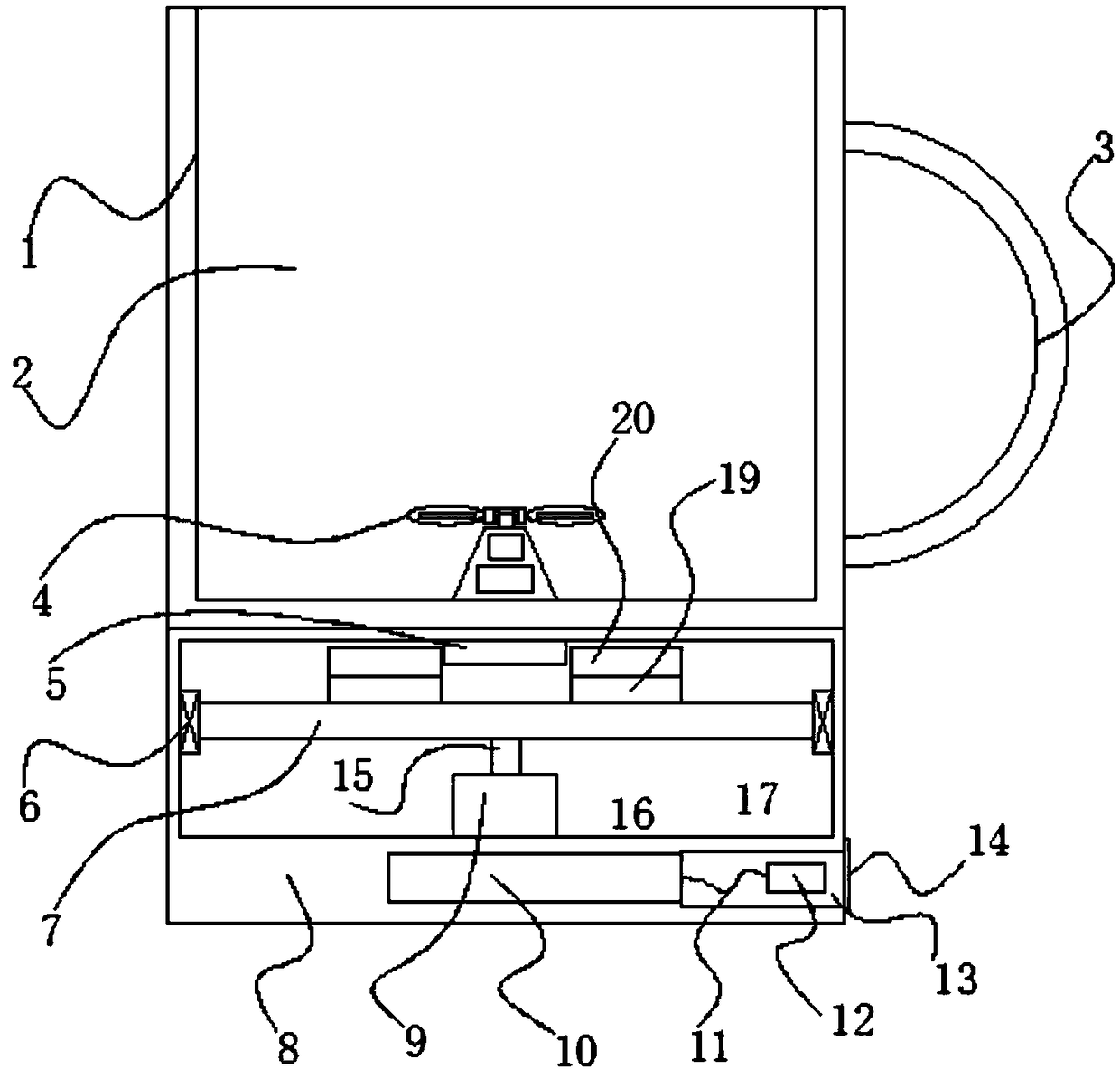
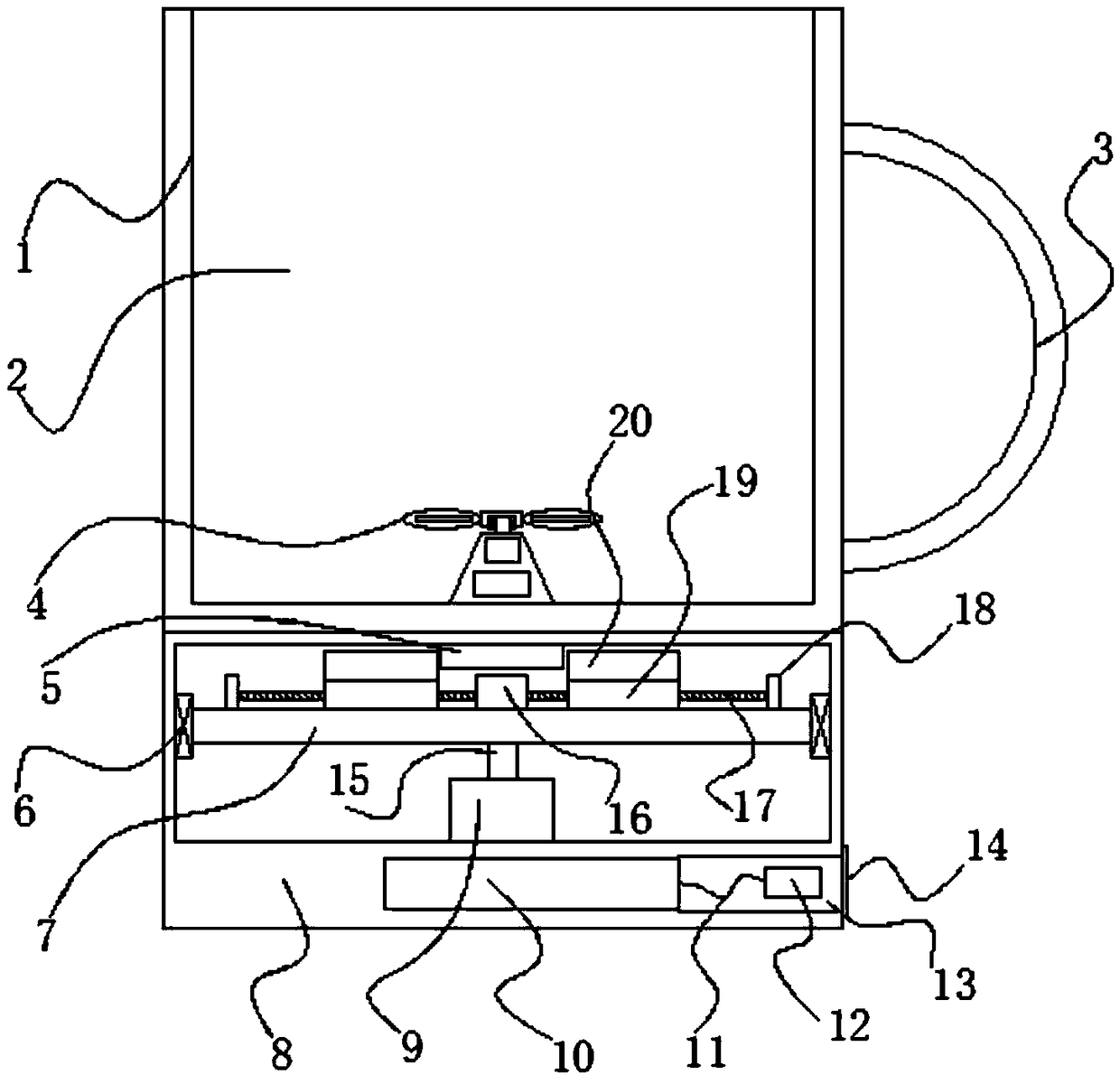
[0023] see Figure 1~3 , in an embodiment of the present invention, a magnetic stirring cup includes a cup body 1, a cup cavity 2 is provided inside the cup body 1, a handle 3 is provided on the right side of the cup body 1, and a drive fixing is provided at the bottom of the cup body 1. The seat 8 and the cup body 1 are provided with a blade mechanism inside, and the drive fixing seat 8 is provided with a drive chamber and a magnetic drive mechanism located in the drive chamber for driving the blade mechanism to rotate.
[0024] The magnetic driving mechanism is electrically connected to the control panel, and the control panel is provided with a control button, and the control panel is electrically connected to the storage battery 10, and the storage battery 10 is provided with a USB charging interface.
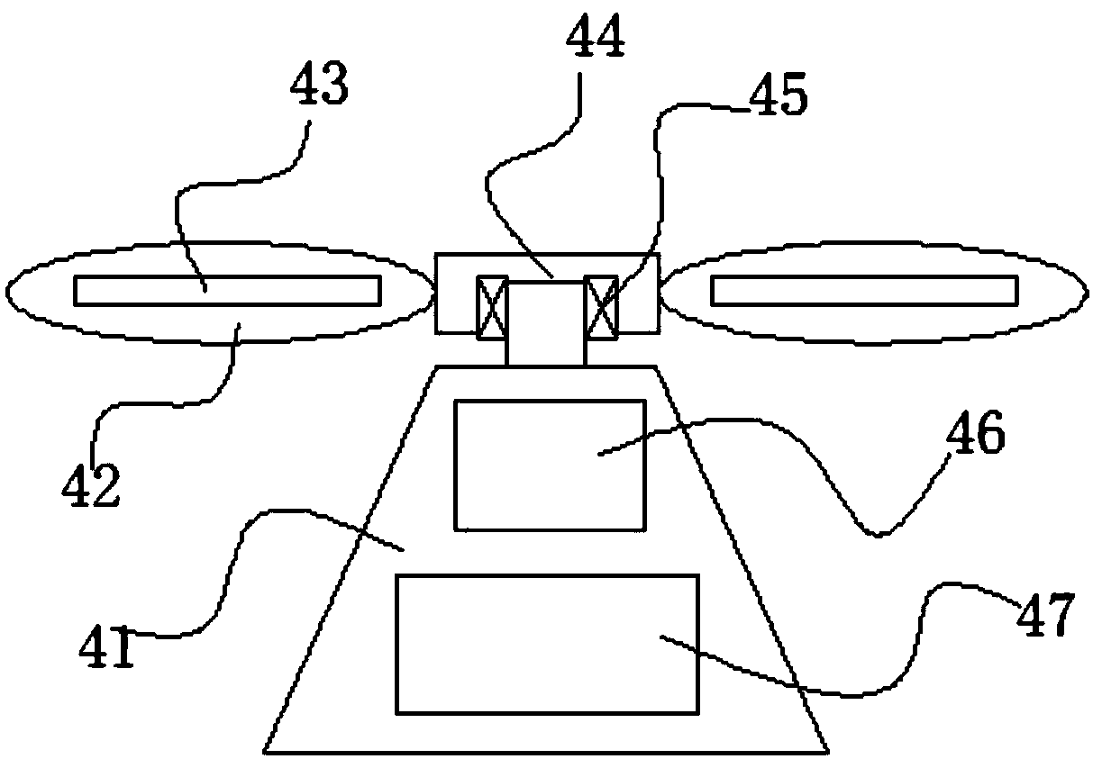
[0025] The fan blade mechanism comprises a conical platform 41, the upper end of the conical platform 41 is provided with a rotating rod 44, the upper end of the rotating r...
Embodiment 2
[0029] The difference from Embodiment 1 is that the sliding seat 19 and the rotating plate 7 are connected and fixed by a screw adjusting mechanism, and the screw adjusting mechanism includes a double-headed motor 16 located in the middle of the upper end of the rotating plate 7, and the output of the double-headed motor 16 The end is provided with transmission screw rod 17, and the outer end of transmission screw rod 17 is rotationally connected with bearing seat 18. Under the action, the sliding block 19 drives the driving magnet 20 to approach or move away, thereby adjusting the distance between the two driving magnets, so as to be suitable for the use of blades 42 with different diameters. After all, the blades 42 needed for relieving heat will be larger.
Embodiment 3
[0031] What differs from embodiment 2 is that both sides of the lower end of the sliding block 19 are symmetrically provided with pulleys, and the rotating plate 7 is provided with a chute matching with the pulleys, so that the distance between the sliding block 19 and the rotating plate 7 will be reduced. friction.
PUM
 Abstract
Description
Claims
Application Information