Check patentability & draft patents in minutes with Patsnap Eureka AI!

Hydraulic lifting appliance

A spreader and hydraulic technology, applied in the direction of load hanging components, cranes, walking bridge cranes, etc., can solve the problems of inability to achieve alignment, low efficiency, and inability to automatically rotate, etc., to achieve convenient operation, accurate positioning, and structure compact effect

Inactive Publication Date: 2019-02-01
常州华睿新能源汽车发展有限公司
View PDF1 Cites 0 Cited by
  • Summary
  • Abstract
  • Description
  • Claims
  • Application Information

AI Technical Summary

Problems solved by technology

[0003] In order to overcome the following problems in the prior art, most of the existing container spreaders use very simple spreaders. The simple spreaders can neither achieve alignment during hoisting, nor can they automatically rotate in the horizontal direction, and the positioning is not correct during operation. precise, inefficient

Method used


Image

  • Hydraulic lifting appliance
  • Hydraulic lifting appliance

Examples


Embodiment Construction

[0017] The present invention will be described in further detail below in conjunction with the accompanying drawings and embodiments. It should be understood that the specific embodiments described here are only used to explain the present invention, not to limit the present invention.

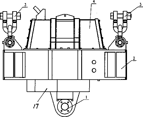
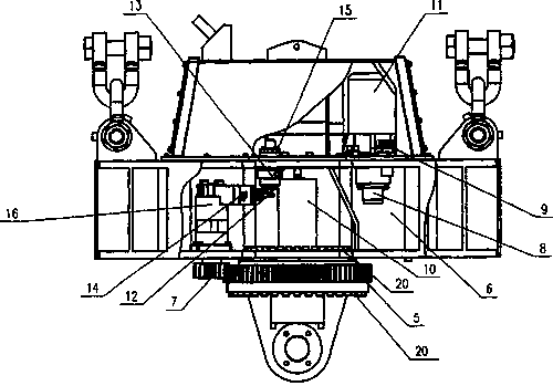
[0018] Such as Figure 1-Figure 2 As shown, the present invention schematically shows a hydraulic hoist.

[0019] The invention discloses a hydraulic sling, such as figure 1 As shown, it includes box body 2, lifting lug 1, lifting lug 3, slewing mechanism and hydraulic device. The symmetrically arranged lifting lug 3 is located on both sides above the box body 2, and the lifting lug 3 is connected with the box body 2. The lifting lug 1 is located at Below the center of the box body 2, a rotary mechanism is set between the box body 2 and the lifting ear 1. The rotary mechanism includes a large gear 5 and a small gear 7. The large gear 5 and the small gear 7 mesh with each other. The large gea...


PUM


Abstract

The invention provides a hydraulic lifting appliance. The hydraulic lifting appliance comprises a box body, a first lifting lug, second lifting lugs, a swing mechanism and a hydraulic device, whereinthe second lifting lugs are connected with the box body, and the first lifting lug is located below the center of the box body; the swing mechanism is arranged between the box body and the first lifting lug, the swing mechanism comprises a big gear and a pinion gear, the big gear and the pinion gear are connected with each other in a meshed mode, the big gear is located on the outer ring of the swing mechanism, and the lower end face of the big gear is fixedly connected with the first lifting lug; and the inner ring of the swing mechanism is fixedly connected with a box body at the upper part,the pinion gear is connected with the hydraulic device located inside the box body, and the pinion gear is driven to rotate. The swing mechanism similar to a bearing is arranged between the box bodyand the first lifting lug, so that mutual rotation between the first lifting lug and the second lifting lugs in the horizontal direction can be realized; the pinion gear is driven by an oil motor to drive the big gear to rotate, so that accurate rotation of the lifting lugs can be conveniently realized through hydraulic control, and then accurate positioning is realized; and the hydraulic liftingappliance is compact in structure and convenient to operate,

Description

technical field [0001] The invention relates to the technical field of hoists, in particular to a hydraulic hoist. Background technique [0002] Most of the existing container spreaders are very simple spreaders. This simple spreader can neither realize alignment during hoisting nor automatically rotate in the horizontal direction. It is very inconvenient to operate and low in efficiency. Sometimes the rotation of the container spreader is driven by the trolley of the crane, but its operation is still inconvenient and its adaptability is poor, so it is not suitable for some special places or occasions without a crane; for example, the patent application number is "92211221.5" published A container gantry crane lower slewing spreader is developed. The main structure is that the motor drives the small gear through the transmission and then drives the large gear to rotate. The large gear drives the spreader bracket to rotate through the bolt group. The large gear cooperates wit...

Claims


Application Information

Patent Timeline
Patent Type & Authority Applications(China)
IPC IPC(8): B66C1/10B66C17/20
CPCB66C1/10B66C17/20
Inventor 李小嫚
Owner 常州华睿新能源汽车发展有限公司
Features
  • R&D
  • Intellectual Property
  • Life Sciences
  • Materials
  • Tech Scout
  • Unparalleled Data Quality
  • Higher Quality Content
  • 60% Fewer Hallucinations
Learn More