
Coil Transport Auxiliary Device

An auxiliary device and steel coil technology, applied in the field of transportation, can solve the problems of large steel coil quality, broken rope, and cumbersome fixing methods.

Active Publication Date: 2020-07-28
安徽跨宇钢结构网架工程有限公司
View PDF6 Cites 0 Cited by
  • Summary
  • Abstract
  • Description
  • Claims
  • Application Information

AI Technical Summary

Problems solved by technology

[0003] In China, the most common way to transport steel coils is "civilian earthwork", laying wooden boards and sleepers at the bottom of the trailer to fix them, but this fixing method is still cumbersome, and the steel coils need to be repeatedly tied to the fixing hooks on the truck base with steel ropes; Moreover, when the car is turning or stopping suddenly, due to the large mass of the steel coil, under the action of huge inertial force, it will often produce an instantaneous huge pulling force on the pull rope on one side, and even cause the accident that the rope breaks and the steel coil falls. But they don't know it; this requires an auxiliary transportation device that reminds the driver of the transportation status of the steel coil in time

Method used


Image

  • Coil Transport Auxiliary Device
  • Coil Transport Auxiliary Device
  • Coil Transport Auxiliary Device

Examples


Embodiment Construction

[0027] The following will clearly and completely describe the technical solutions in the embodiments of the present invention with reference to the accompanying drawings in the embodiments of the present invention. Obviously, the described embodiments are only some, not all, embodiments of the present invention.

[0028] In describing the present invention, it should be understood that the terms "upper", "lower", "front", "rear", "left", "right", "top", "bottom", "inner", " The orientation or positional relationship indicated by "outside", etc. is based on the orientation or positional relationship shown in the drawings, and is only for the convenience of describing the present invention and simplifying the description, rather than indicating or implying that the referred device or element must have a specific orientation, so as to Specific orientation configurations and operations, therefore, are not to be construed as limitations on the invention.

[0029] refer to Figure ...


PUM


Abstract

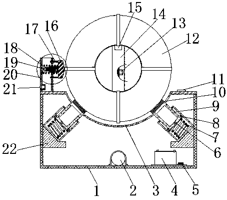
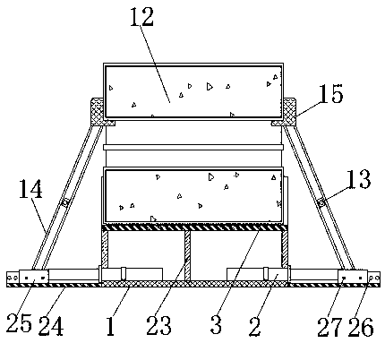
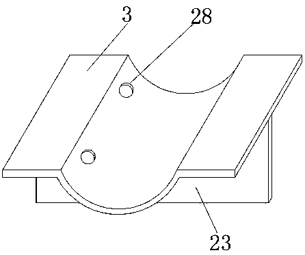
The invention belongs to the technical field of steel coil transportation and particularly relates to a steel coil transportation auxiliary device. The steel coil transportation auxiliary device aimsto solve the problems that in the prior art, when a steel coil is fixed, the steel coil needs to be bundled with a steel wire rope by several circles to a truck, and when the truck turns, the steel wire rope can be snapped due to large inertia. According to the technical scheme, the steel coil transportation auxiliary device comprises a channel steel base and a steel coil. A storage battery and aprocessor are arranged on the inner wall of the bottom of the channel steel base and are close to the edge portion. The middle and the portions, close to the two side edges, of the upper surface of the channel steel base are both provided with supporting plates in a welded manner. The same upper base plate is welded to the top ends of the three supporting plates. The steel coil transportation auxiliary device can rapidly and tightly fix the left side and the right side of the steel coil, stress detectors on H-type steel web plates can transmit the pressure force of the steel coil on supportingrods and the stress condition of the supporting rods in time, and when the stress of the supporting rods excessively exceeds the limit value of the supporting rods, the stress detectors can transmitsignals to the processor in time, and then an alarm is triggered to notice a transportation driver to conduct reinforcing treatment in time.

Description

technical field [0001] The invention relates to the technical field of transportation, in particular to a steel coil transportation auxiliary device. Background technique [0002] When it comes to steel coils, I believe that the first reaction in the minds of many card users is "the poor will not pull the tube, the starved will not pull the coil, and the dead will not pull the green pass", because in the steel coil transportation industry, incorrect operations , binding, etc. caused countless accidents, making many card friends talk about "steel" discoloration. [0003] In China, the most common way to transport steel coils is "civilian earthwork", laying wooden boards and sleepers at the bottom of the trailer to fix them, but this fixing method is still cumbersome, and the steel coils need to be repeatedly tied to the fixing hooks on the truck base with steel ropes; Moreover, when the car is turning or stopping suddenly, due to the large mass of the steel coil, under the a...

Claims


Application Information

Patent Timeline
Patent Type & Authority Patents(China)
IPC IPC(8): B65D61/00B65D85/66
CPCB65D61/00B65D85/66
Inventor 朱祝雷
Owner 安徽跨宇钢结构网架工程有限公司
Learn More