A precision compensation method for a split resolver for a position marker

A resolver and precision compensation technology, which is applied in the direction of instruments, general control systems, adaptive control, etc., can solve problems such as poor precision

Active Publication Date: 2021-06-15
BEIJING INST OF REMOTE SENSING EQUIP
View PDF16 Cites 0 Cited by
  • Summary
  • Abstract
  • Description
  • Claims
  • Application Information

AI Technical Summary

Problems solved by technology

[0003] The purpose of the present invention is to provide a method for compensating the accuracy of a split rotary transformer coaxially installed

Method used


Image

  • A precision compensation method for a split resolver for a position marker
  • A precision compensation method for a split resolver for a position marker

Examples


Embodiment 1

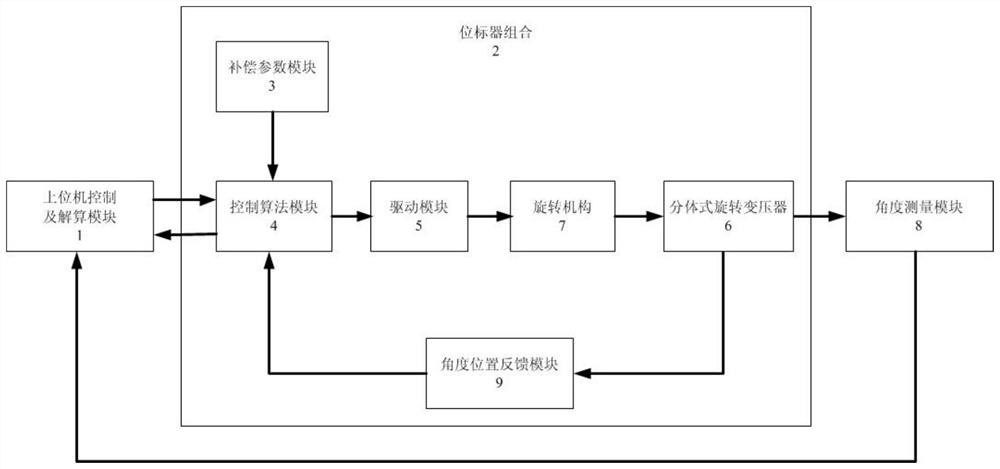
[0022] A device and method for improving the compensation of a split resolver, comprising: a host computer control and calculation module 1, a position marker combination 2, a compensation parameter module 3, a control algorithm module 4, a drive module 5, a split resolver 6, a rotary Mechanism 7, angle measurement module 8 and angle position feedback module 9.

[0023] Wherein, the compensation parameter module 3 , the control algorithm module 4 , the driving module 5 , the split resolver 6 , the rotating mechanism 7 and the angle position feedback module 9 belong to the position marker combination 2 .

[0024] The two communication ends of the upper computer control and calculation module 1 are respectively connected to the communication port of the angle measurement module 7 at the position marker combination 2, the angle measurement module 8 is fixed on the rotating mechanism 7, and the split resolver 6 is coaxially installed On the rotating mechanism 7 and rotate thereupo...

Embodiment 2

[0026] Using the compensation method of the above-mentioned position marker with a coaxially installed split resolver precision compensation system, the specific steps are:

[0027] Step 1: Fix the angle measurement module 8 on the rotating mechanism 7 .

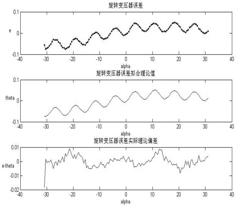
[0028] Step 2: The upper computer control and calculation module 1 presets the angle through communication with the position marker combination 2 and reads the electrical feedback angle α of the split resolver 6 1 At the same time, the upper computer control and calculation module 1 reads the actual rotation mechanical angle β of the split resolver 6 and the rotation mechanism 7 through communication with the angle measurement module 8 1 , the host computer control and calculation module 1 calculates the electrical feedback angle α of the split resolver 6 1 and the actual rotation mechanical angle β 1 Error e 1 = β 1 -α 1 .

[0029] Step 3: By repeating the above process, averagely take n angles within the range of mot...


PUM


Abstract

The invention discloses a split rotary transformer precision compensation system and method for a position marker. The system includes: a host computer control and calculation module (1), a position marker combination (2), a compensation parameter module (3), and a control algorithm A module (4), a drive module (5), a split rotary transformer (6), a rotary mechanism (7), an angle measurement module (8) and an angle position feedback module (9). After testing the output angle of the split resolver (6) and the angle position feedback module (9) through this set of devices, the actual mechanical rotation angle error is measured and the fitting curve function is calculated, and the accuracy of the resolver measurement value is significantly improved after compensation using this function. The present invention makes corresponding compensation for the electric feedback angle of the coaxially installed split resolver (6) for the position marker without adding additional hardware logic circuits, and effectively improves the measurement accuracy of the coaxially installed split resolver for the position marker .

Description

technical field [0001] The invention relates to a method for improving the precision of a rotary transformer for a position marker, in particular to a method for compensating the precision of a coaxially installed split rotary transformer for a position marker. Background technique [0002] The position marker is a servo combination that can be used to precisely control the rotation angle of the antenna and feed back the actual rotation angle of the antenna to other combinations. Its performance directly affects the control accuracy of the antenna beam pointing. The resolver is a key device for the position marker to measure the rotation angle, and the read angle accuracy of the resolver directly affects the accuracy of the position marker feedback and preset accuracy. In order to improve the angular accuracy of the resolver, it needs to be calibrated and compensated. However, the electrical error characteristics of the resolver itself can only be determined after the split...

Claims


Application Information

Patent Timeline
IPC IPC(8): G05B13/02
CPCG05B13/024
Inventor 薛志刚王小磊李春文文哲
Owner BEIJING INST OF REMOTE SENSING EQUIP
Why Eureka
Try Eureka