Method for regulating micro print ink dot position and size

A kind of ink dot and tiny technology, applied in the electrical recording process using the charge pattern, the equipment of the electric recording process using the charge pattern, and the electrography, etc., can solve the problems that affect the printing quality, are not proportional, and errors, etc., to achieve Effects that improve print quality

Inactive Publication Date: 2008-03-26
BEIJING FOUNDER ELECTRONICS CO LTD +1
View PDF7 Cites 0 Cited by
  • Summary
  • Abstract
  • Description
  • Claims
  • Application Information

AI Technical Summary

Problems solved by technology

[0012] 1) The existing halftone technology is based on a strict mathematical model, and it is assumed that the printer can accurately print any grayscale within the predetermined grayscale level when printing each pixel. In the 
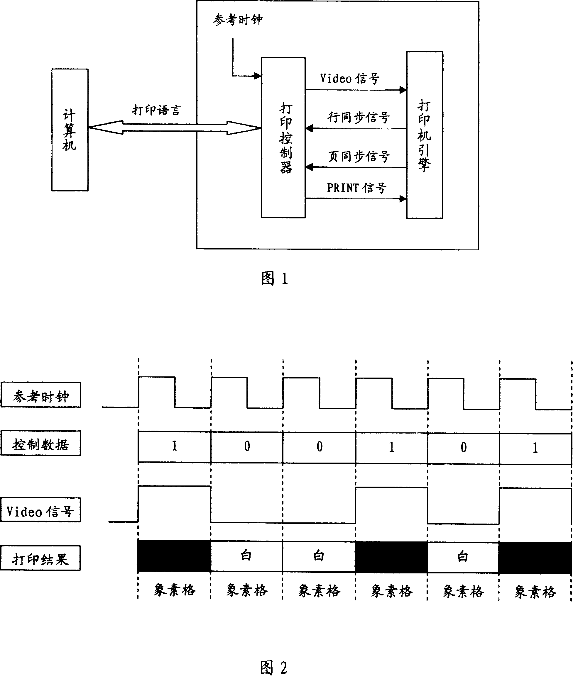
bitmap, there will be a large number of dots with very low gray levels, that is, dots with small ink dots, so that the gray scale of the pixel is directly used as the pulse width control information for controlling the pixel to generate corresponding pulse width modulator. The video signal used to control the printer engine will produce many isolated tiny ink dots, and the printing of these isolated tiny ink dots is very unstable, or even unable to print out, which will seriously affect the quality of printing
[0013] 2) Although, according to the imaging principle of a laser printer, the width of the laser pulse printed by a pixel determines the amount of ink in the pixel grid, thereby determining the final grayscale printed by the pixel, that is, the grayscale of a pixel The degree of intensity level is linearly proportional to the size of the ink dot and the pulse width acting on the pixel, but in fact, because of the influence of the particle size of the toner, the actual physical characteristics of the toner and the toner cartridge, this correspondence is often not proportional
Moreover, for tiny ink dots, the size of the ink dots is not completely proportional to the pixel gray scale observed by the human eye. There is a large error between the grayscale of the pixel and the grayscale predicted by the existing halftone technology, which affects the print quality
[0014] 3) The laser generator in the existing laser printer usually has certain restrictions on the pulse width produced by the controller, that is, the pulse width cannot be less than a certain threshold value. In this way, the gray scale of the pixel is directly used as The method of controlling the pulse width of the pixel to control the pulse width modulator will lead to some uncertain results, so the printing effect will also be affected
[0015] In order to further improve the printing quality, on the basis of the usual 
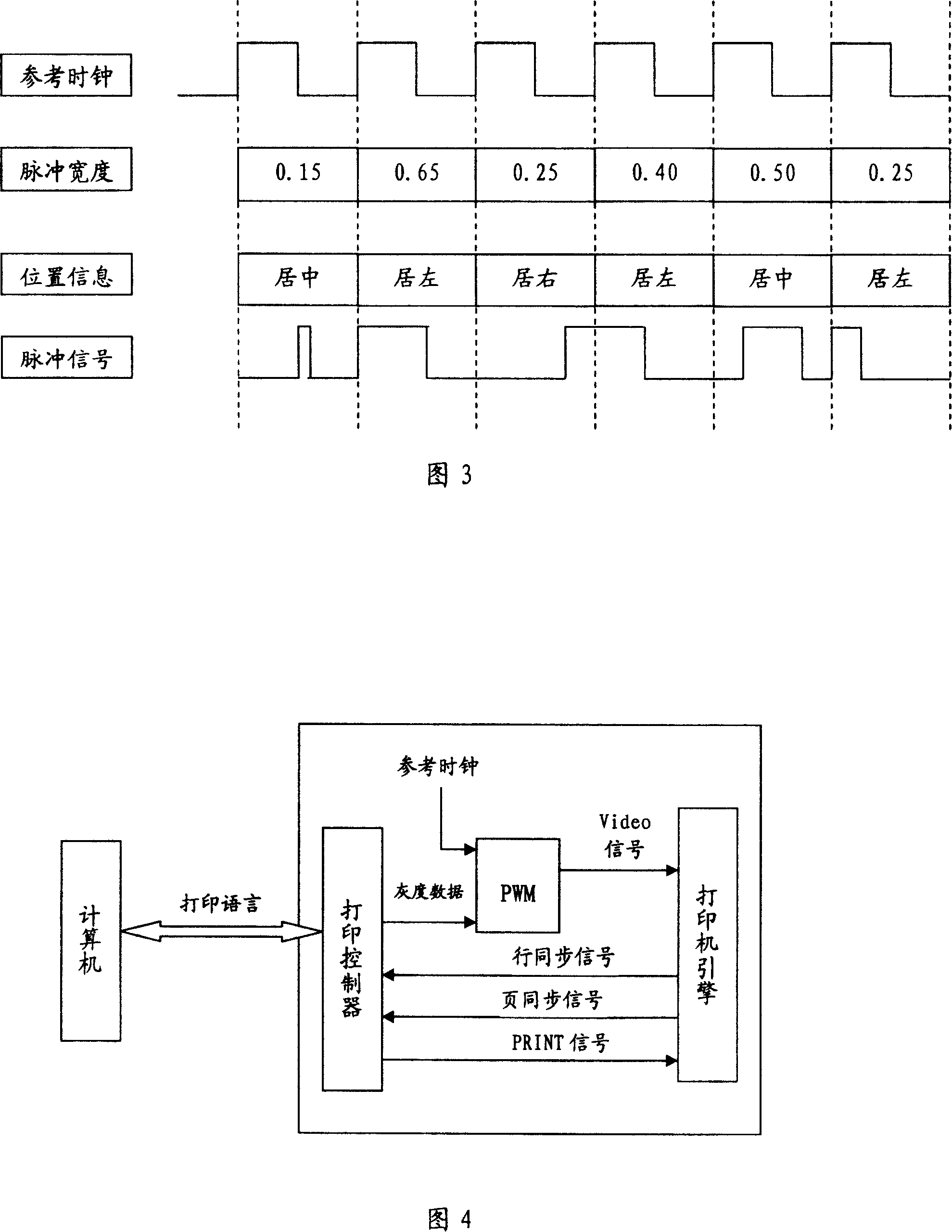
pulse width modulation technology, some improved methods have appeared. For example, Ricoh proposed a method to adjust the current pixel according to the gray scale of adjacent pixels in US Patent 5,144,338. position to merge pixels, but this method does not use the position information of the previous adjacent pixel when adjusting the current pixel position. This method can only achieve better results when printing text, because if the content to be printed is Text, then in the multi-bit 
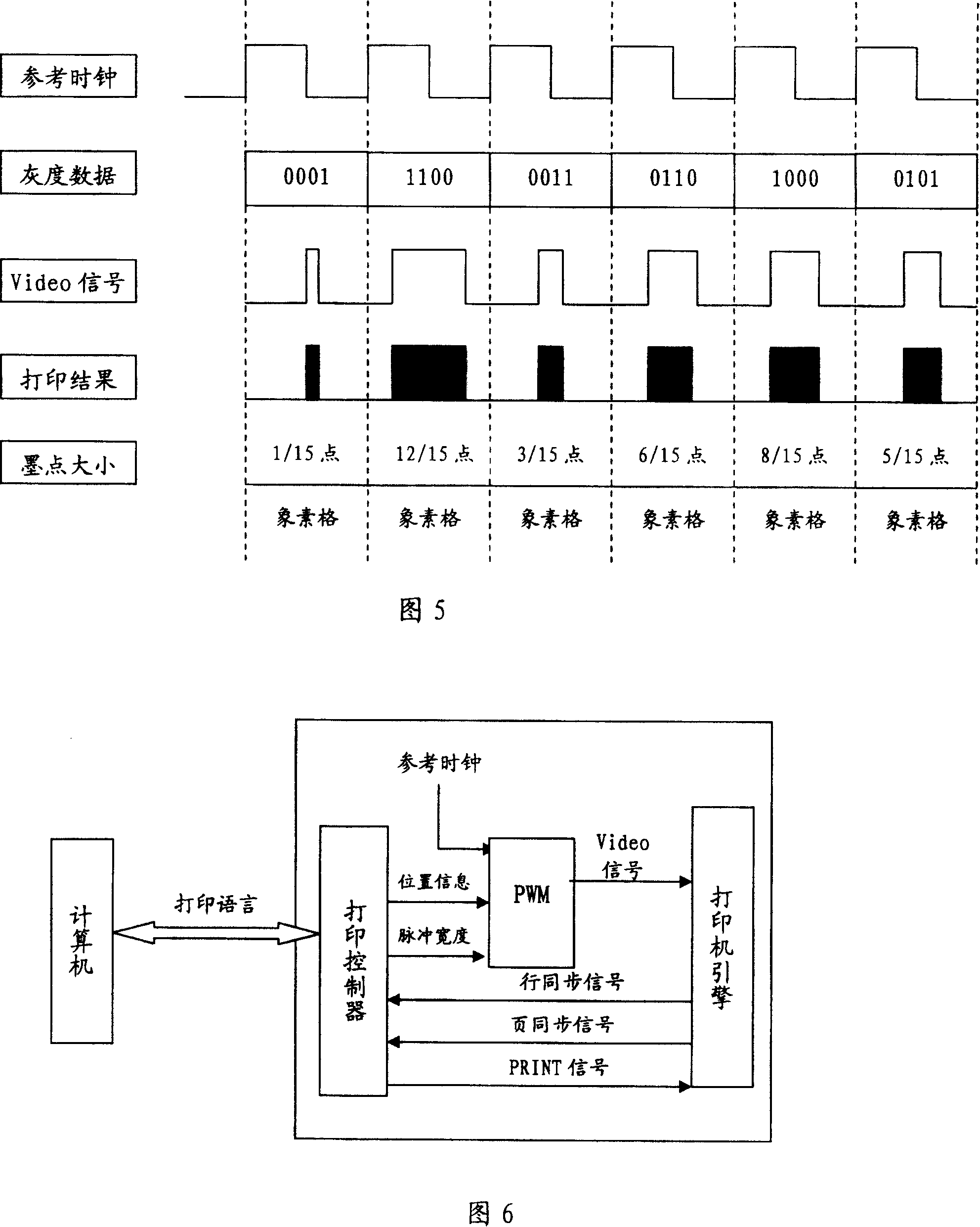
bitmap produced by the text, the tiny ink dots only appear on the edges of the strokes of the characters, and the method described in this patent can be used to merge the tiny ink dots on the edges of the text, but when using 8-bit images In the multi-bit bitmap produced by the existing halftone technology, there are often a large number of tiny ink dots, which are all adjacent and may have the same gray scale. In this way, using the method described in this patent, the positions of these tiny ink dots will still be different. Centered, so there will be a large number of tiny ink dots that cannot be merged into larger ink dots, and the method described in this patent directly maps the gray scale of each pixel to the pulse width first, so that the ink with extremely small gray scale Points will be discarded at first, and at the same time, if 2 adjacent tiny pixels are merged, the pixel grayscale printed by the pulse width obtained by this method is the same as that of the 2 adjacent images predicted by the existing halftone technology. Compared with the sum of the gray value of the pixel, there is often a considerable error, and the method described in the patent neither considers that the correspondence between the gray level of the pixel and the pulse width is a non-linear proportional relationship and adjusts the pulse width corresponding to the pixel, nor does it Consider the effect of the threshold value of the laser generator, all of which will affect the print quality of multi-bit bitmaps produced according to existing halftoning techniques using the method described in this patent

Method used


Image

  • Method for regulating micro print ink dot position and size
  • Method for regulating micro print ink dot position and size
  • Method for regulating micro print ink dot position and size

Examples


Embodiment Construction

[0045] The present invention will be further described below in conjunction with the accompanying drawings.

[0046] Figure 1 describes a block diagram of an ordinary laser printer, which includes two parts: the printer engine and the print controller. The reference clock is a synchronous control signal that controls the output data of the print controller and the synchronization of the laser beam of the printer engine. Its period is equal to the laser beam scanning of the printer. The time of a complete pixel, such as the printer laser beam scanning a complete pixel time is 50ns, then the reference clock cycle is also 50ns. When printing, the print controller receives the page printing data from the computer, interprets the page printing data into a raster dot matrix, and converts the raster dot matrix into a Video signal through control signals such as page synchronization signal, line synchronization signal, and PRINT signal, thereby controlling the printer The engine finis...


PUM


Abstract

This invention belongs to printing control technical filed, particularly refer to a method of adjusting location and size of minim ink smudge. Printing technique now available affects print quality, because it always uses minim pixel directly as pulse width which controls print. The method of this invention is that install pulse width compensation form firstly, secondly define page data as multi-position bitmap, thirdly calculate every pixel's positional information according to tonal value of the pixel's next in the same scan line and adjust corresponding pulse width of the same pixel, lastly control pulse width modulator with adjusted pulse width value and position information to print. Adopt the method of this invention could merge unstable printing minim ink smudge into stabilized printing fair-sized ink smudge, simultaneously make the size of minim ink smudge conform to the physical property of typewriter, thereby improve print quality by far.

Description

technical field [0001] The invention belongs to the technical field of printing control, and in particular relates to a method for adjusting the position and size of tiny printing ink dots. Background technique [0002] The core technology of laser printer is exactly electronic imaging technology, and its core component is a photosensitive toner cartridge. The laser light emitted by the laser transmitter is irradiated on a prismatic reflector. As the reflector rotates, the light sweeps from one end of the drum to the other in turn, and the drum rotates in steps of 1 / 300 inch or 1 / 600 inch. , and the scan is performed on the next line. The toner cartridge is a cylinder that has been coated with organic material on a surface, has electric charge in advance, and when light shone, changes in resistance can take place at the position being shone. The data signal sent by the controller controls the emission of the laser, and the light scanned on the surface of the toner drum is ...

Claims


Application Information

Patent Timeline
Patent Type & Authority Patents(China)
IPC IPC(8): G03G21/14G03G15/00
Inventor 刘志红
Owner BEIJING FOUNDER ELECTRONICS CO LTD
Why Eureka
Try Eureka