A charging device for new energy vehicles

A technology of new energy vehicles and charging devices, which is applied in the direction of electric vehicle charging technology, charging stations, electric vehicles, etc., can solve problems such as the influence of charging device parts, unfavorable charging line retraction, easy sticking of charging lines, etc., to achieve improved Safety, reduce the probability of entanglement, and improve the effect of service life

Active Publication Date: 2021-12-03
GUANGXI POWER GRID CO LTD NANNING POWER SUPPLY BUREAU +1
View PDF9 Cites 0 Cited by
  • Summary
  • Abstract
  • Description
  • Claims
  • Application Information

AI Technical Summary

Problems solved by technology

[0004] Disadvantages of the existing charging device: when the reel is retracting the charging cable, it can only retract the charging end of the charging cable. When not charging, it does not store the charging end of the charging cable. It is not conducive to the retracting and retracting of the charging cable, and when the gun head is charging, the charging cable is easy to stick to dirt and other impurities. Impurities are not only not conducive to the retracting and retracting of the charging cable, but also affect the parts of the charging device

Method used


Image

  • A charging device for new energy vehicles
  • A charging device for new energy vehicles
  • A charging device for new energy vehicles

Examples


Embodiment

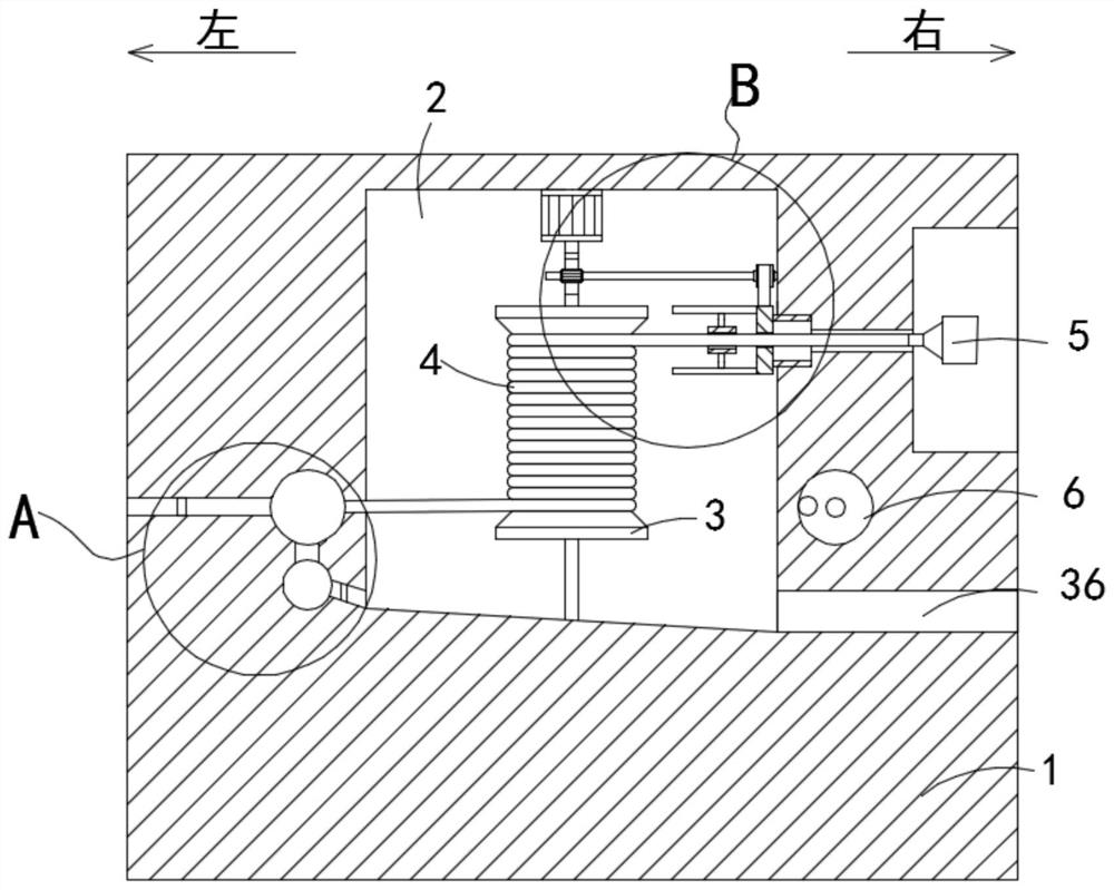
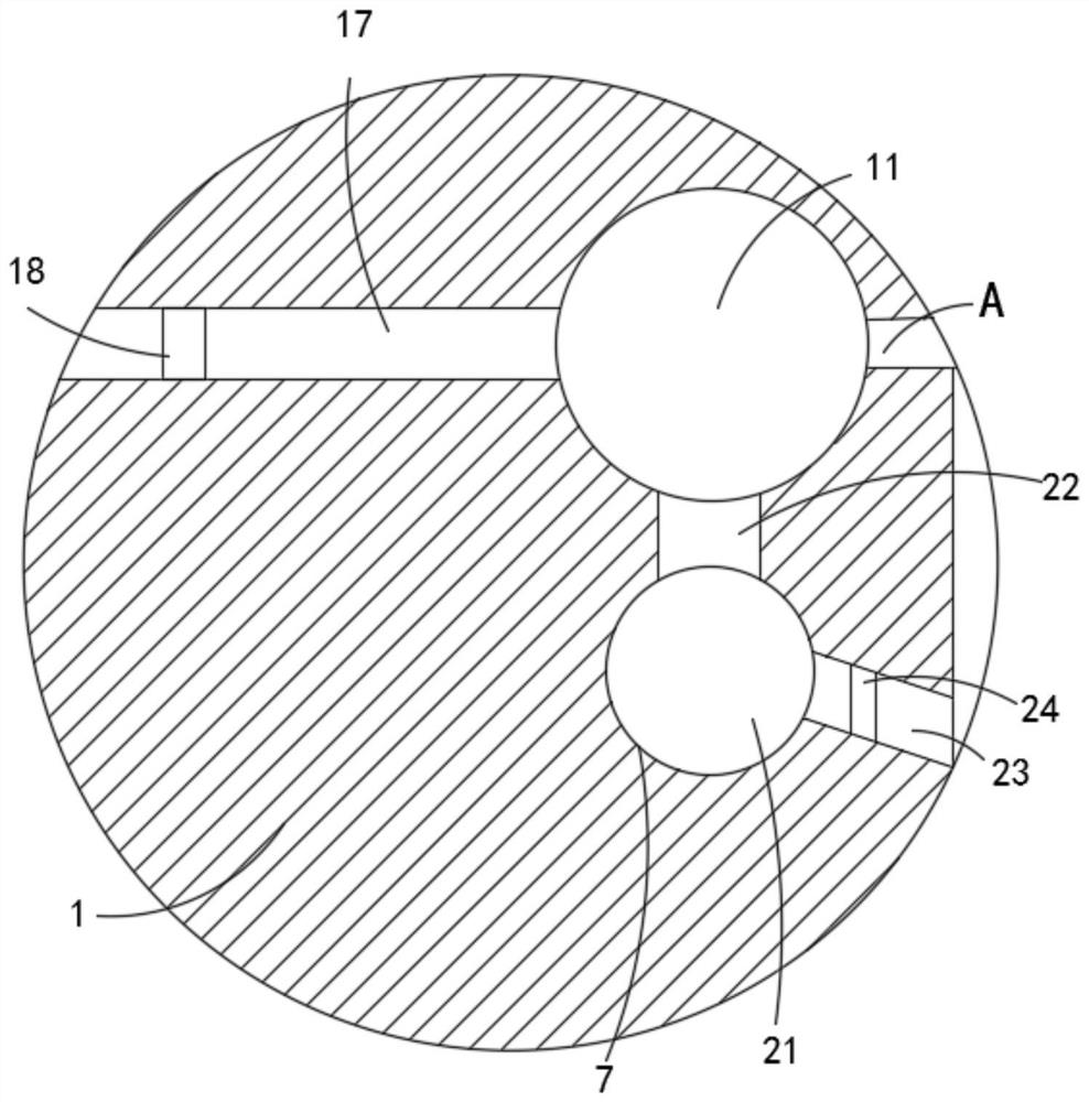
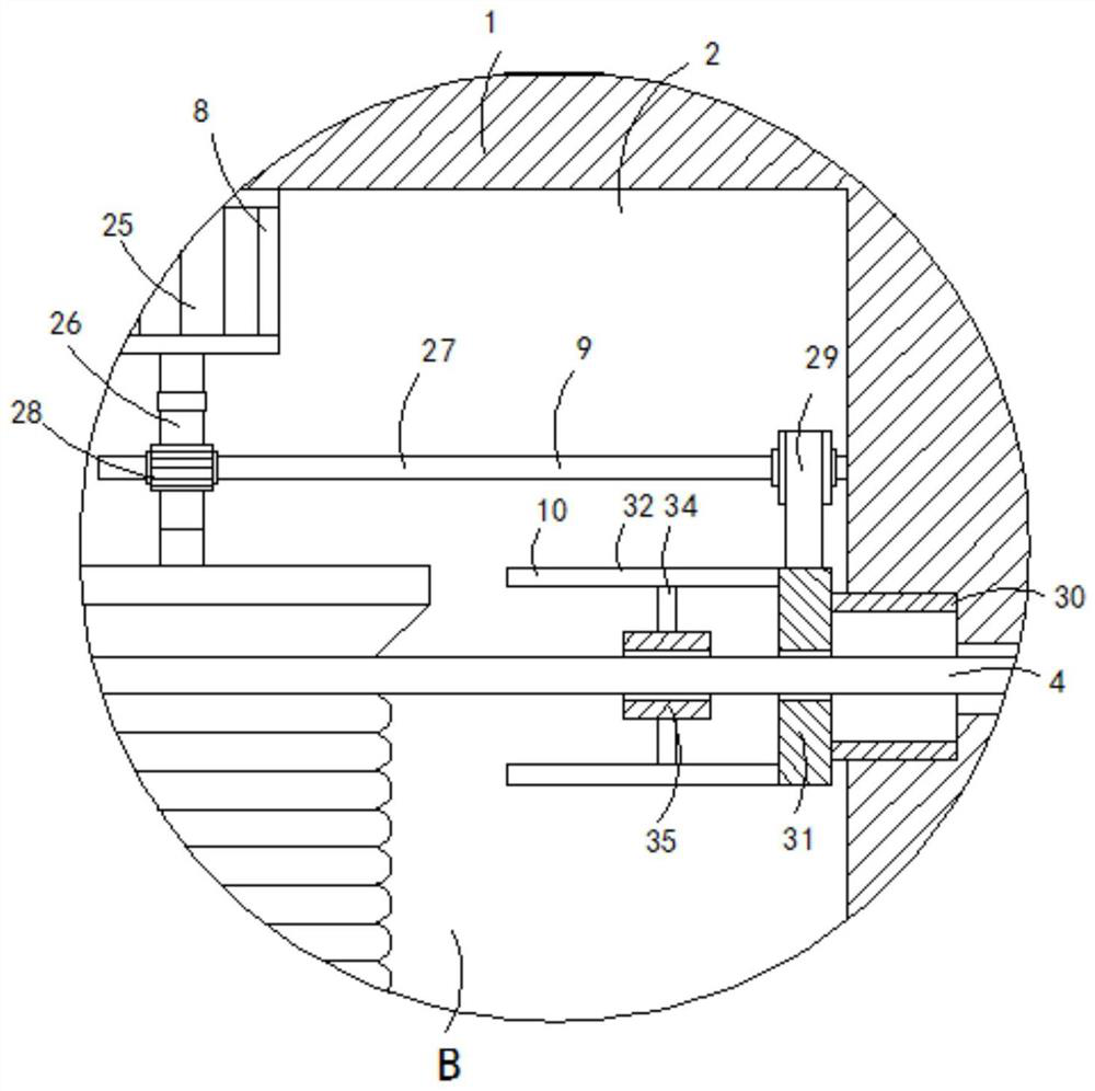
[0028] Such as Figure 1-6 As shown, a charging device for a new energy vehicle includes a charging pile 1. The charging pile 1 is provided with a take-up cavity 2. The bottom of the take-up cavity 2 is rotatably connected to a take-up reel 3, and a charging reel 3 is coiled on the take-up reel 3. line 4, wherein, when the take-up reel 3 rotates, the line body of the charging end of the charging line 4 is separated from the take-up reel 3, and the line body of the charging end of the charging line 4 is wound on the take-up reel 3, and the take-up reel 3 is reversed. When rotating, the charging end can be rewound and wound, and the charging end is separated from it. The charging end of the charging line 4 passes through the inner wall on the right side of the receiving chamber 2 and is electrically connected to the gun head 5. The specific structure and working principle are all existing technologies, and will not be repeated here. The charging pile 1 is provided with a control...


PUM


Abstract

The invention belongs to the technical field of new energy vehicle charging, and in particular relates to a charging device for new energy vehicles, which includes a charging pile, a wire take-up chamber is arranged inside the charging pile, and a wire take-up reel is connected to the bottom of the wire take-up chamber in rotation, and the wire take-up reel There is a charging cable coiled on it, and the charging end of the charging cable passes through the right inner wall of the receiving cavity and is electrically connected to the gun head. The charging pile is equipped with a control mechanism for the charging cable, and the charging cable coil is set in the control mechanism and Electrically connected with it, the control mechanism is covered with the outer side of the wire receiving chamber, and the charging pile is equipped with an air injection mechanism connected with the bottom of the control mechanism. A driving mechanism is arranged, and the driving end of the driving mechanism is fixedly connected with the upper end of the wire take-up reel, and a transmission mechanism is rotatably connected on the right side inner wall of the wire take-up chamber. The advantage is that the present invention can effectively accommodate the charging end of the charging line, and can also descale the charging line.

Description

technical field [0001] The invention belongs to the technical field of new energy vehicle charging, and in particular relates to a charging device for new energy vehicles. Background technique [0002] New energy vehicles refer to all other energy vehicles except gasoline and diesel engines. Including fuel cell vehicles, hybrid vehicles, hydrogen energy vehicles and solar vehicles. Its exhaust emissions are relatively low. [0003] After searching, the patent number: CN106945557B discloses a charging device for new energy vehicles, including a charging pile and a car interface. The charging pile is provided with a take-up cavity, and the outer end surface of the charging pile on the right side of the take-up cavity is provided with an operation slot. There is a through hole between the operation slot and the wire take-up cavity. The inner bottom wall on the right side of the wire take-up cavity is longitudinally provided with a first chute whose top communicates with the w...

Claims


Application Information

Patent Timeline
Patent Type & Authority Patents(China)
IPC IPC(8): B60L53/31B60L53/14B60L53/18
CPCY02T10/70Y02T10/7072Y02T90/12Y02T90/14
Inventor 尹永远刘煜东孙睿国家栋
Owner GUANGXI POWER GRID CO LTD NANNING POWER SUPPLY BUREAU
Why Eureka
Try Eureka