Supercharge Your Innovation With Domain-Expert AI Agents!

Sealing device of rolling rotor compressor and rolling rotor compressor

A rolling rotor type, sealing device technology, applied in the sealing device of piston pump, rotary piston type machinery, machine/engine, etc., can solve problems such as leakage, and achieve the effect of improving sealing

Active Publication Date: 2021-03-12
SHANGHAI HITACHI ELECTRICAL APPLIANCES CO LTD
View PDF8 Cites 0 Cited by
  • Summary
  • Abstract
  • Description
  • Claims
  • Application Information

AI Technical Summary

Problems solved by technology

[0007] The object of the present invention is to provide a sealing device of a rolling rotor compressor and a rolling rotor compressor, so as to solve the problem that the refrigerant in the existing rolling rotor compressor flows from the high pressure chamber through the gap between the sliding plate and the cylinder end cover. Technical Problems of Low Pressure Chamber Leakage

Method used


Image

  • Sealing device of rolling rotor compressor and rolling rotor compressor
  • Sealing device of rolling rotor compressor and rolling rotor compressor
  • Sealing device of rolling rotor compressor and rolling rotor compressor

Examples


Embodiment 1

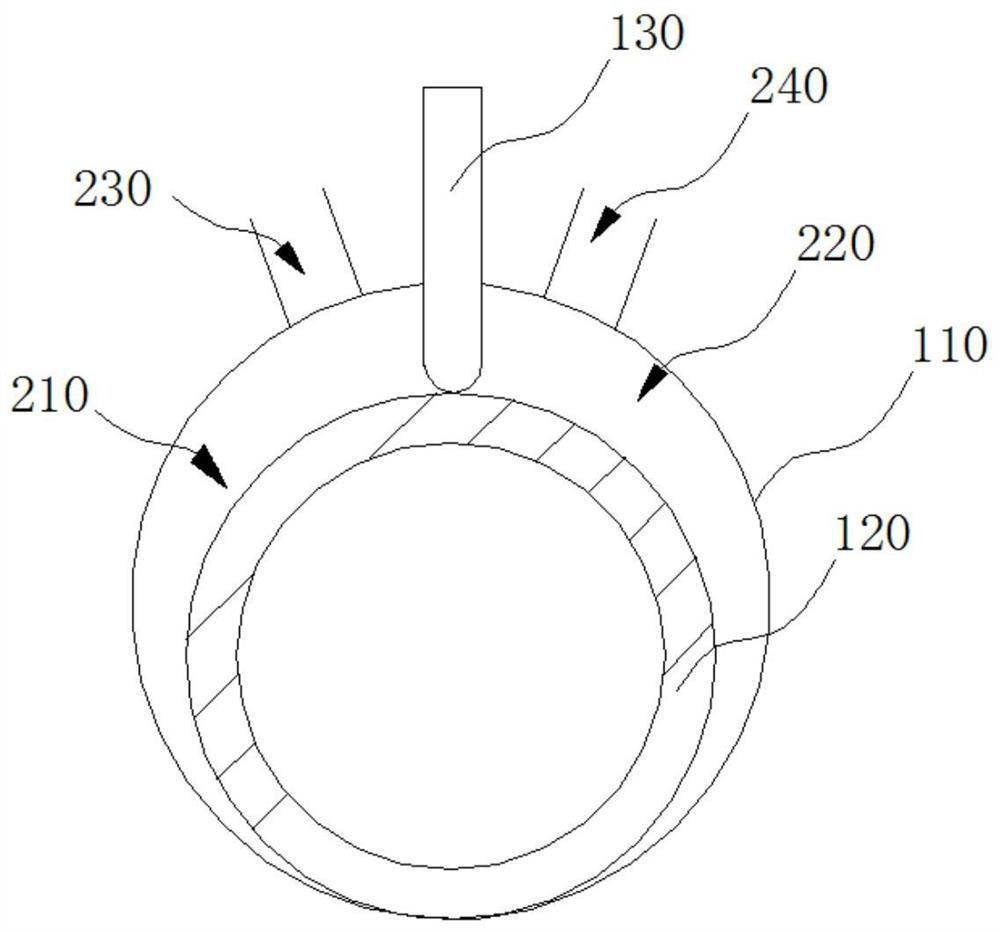
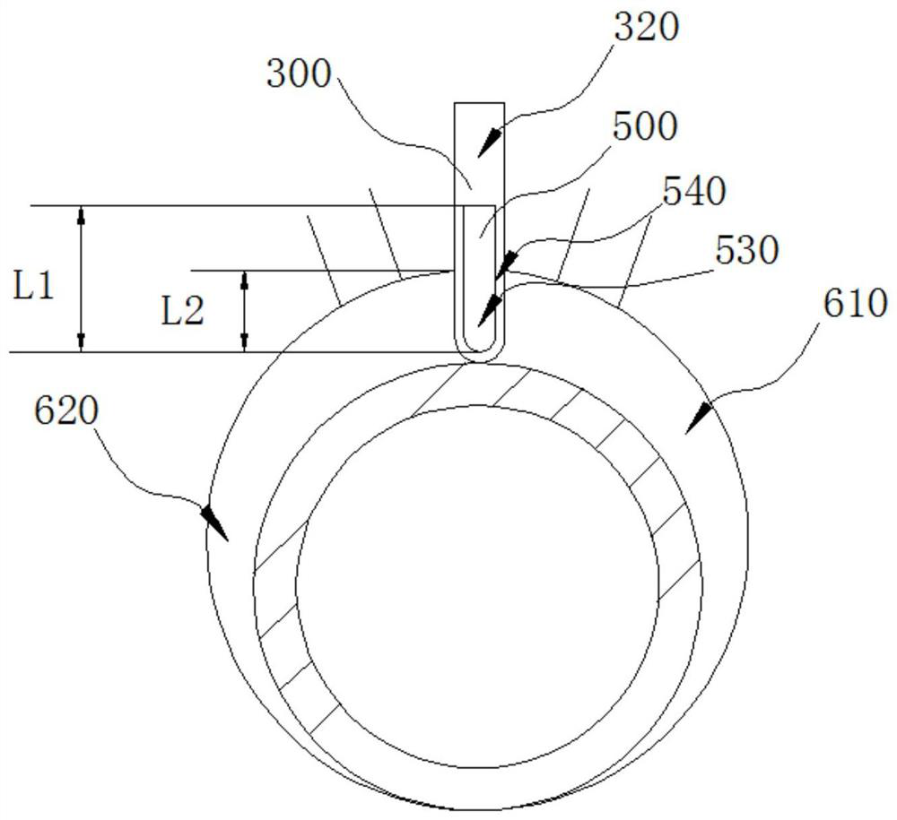
[0050] figure 2 It is a schematic cross-sectional view in one direction of the sealing device of the rolling rotor compressor according to an embodiment of the present invention, image 3 It is a partial cross-sectional schematic view of the sealing device of the rolling rotor compressor in another direction according to an embodiment of the present invention. refer to figure 2 with image 3 , this embodiment provides a sealing device for a rolling rotor compressor, and the sealing device includes a groove 310 and a sealing member 500 . The rolling rotor compressor includes a cylinder head cover 400, a sliding vane 300 and a closed cavity (not shown in the figure). The sliding vane 300 divides the airtight cavity into a high-pressure chamber 610 and a low-pressure chamber 620 , and the high-pressure chamber 610 and low-pressure chamber 620 are respectively located on both sides of the sliding vane 300 . The sliding piece 300 has a first end surface 320 facing the cylinde...

Embodiment 2

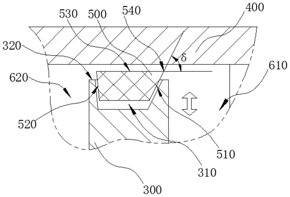
[0060] This embodiment provides a sealing device for a rolling rotor compressor, and the sealing device includes a groove and a sealing member. The rolling rotor compressor includes a cylinder end cover, a sliding vane and a closed cavity. The sliding vane divides the airtight cavity into a high-pressure chamber and a low-pressure chamber, and the high-pressure chamber and low-pressure chamber are respectively located on both sides of the sliding vane. The cylinder end cover has a second end surface facing the sliding piece. The groove is opened on the second end surface. The seal is installed in the groove. The seal has opposing first and second sides, and a sealing surface facing the cylinder head cover. One side of the sealing surface is connected to the first side, and the other side of the sealing surface is connected to the second side. The first side is close to the high pressure cavity, and the second side is close to the high pressure cavity. The included angle δ...

Embodiment 3

[0063] This embodiment also provides a rolling rotor compressor. Figure 4 It is a cross-sectional view of a rolling rotor compressor according to an embodiment of the present invention. refer to Figure 4 , the rolling rotor compressor includes the above-mentioned sealing device of the rolling rotor compressor.

[0064] Preferably, the number of the cylinder end covers 400 is two, and a sealing device of the rolling rotor compressor is provided between the two cylinder end covers 400 and the sliding vane 300 . Especially for horizontal rolling rotor compressors, seals 500 are provided on the two end faces of the sliding vane 300 facing the cylinder end cover 400, which can effectively prevent the refrigerant from passing through the sliding vane 300 and the cylinder end cover 400 from the high pressure chamber. The gap between leaks into the low pressure chamber. Of course, in other embodiments, refer to Figure 4 For example, a vertical scrolling rotor compressor, the ve...


PUM


Abstract

The invention provides a sealing device for a rolling rotor compressor. The rolling rotor compressor comprises a cylinder cover, a slip sheet and a closed cavity. The sealing device comprises a grooveand a sealing part, wherein the groove is formed in a first end surface; the sealing part is mounted in the groove and provided with a first side surface and a second side surface which are oppositeto each other, as well as a sealing face facing the cylinder cover; the first side surface is close to a high-pressure cavity; the second side surface is close to a low-pressure cavity; an included angle between the sealing face and the first side surface is smaller than 90 degrees; and the sealing face is not lower than the first end surface; and the sealing part floats in the direction of approaching or getting away from the cylinder cover relative to the groove. According to the sealing device, a gap between the slip sheet and the cylinder cover is reduced, a refrigerant is prevented from leakage, and the compression efficiency of the rolling rotor compressor is improved.

Description

technical field [0001] The invention relates to the technical field of rolling rotor compressors, in particular to a sealing device of a rolling rotor compressor and a rolling rotor compressor. Background technique [0002] With the improvement of living standards, the demand for refrigeration equipment is increasing. For example, the market demand for refrigerators and air conditioners has reached an astonishing level. As long as refrigeration equipment is involved, compressors are basically used, and compressors are an indispensable component of refrigeration equipment. Among compressors, rolling rotor compressors are widely used in air conditioners, refrigerators and other fields. [0003] Rolling rotor compressors are volumetric compressors. figure 1 It is a partial sectional view of a rolling rotor compressor. refer to figure 1 , The rolling rotor compressor includes a cylinder 110, an eccentric rotor 120, a sliding vane 130 and a cylinder end cover (not shown in th...

Claims


Application Information

Patent Timeline
Patent Type & Authority Patents(China)
IPC IPC(8): F04C18/356F04C27/00
CPCF04C18/3566F04C27/001
Inventor 黄波赵凤荣
Owner SHANGHAI HITACHI ELECTRICAL APPLIANCES CO LTD
Features
  • R&D
  • Intellectual Property
  • Life Sciences
  • Materials
  • Tech Scout
  • Unparalleled Data Quality
  • Higher Quality Content
  • 60% Fewer Hallucinations
Learn More