Supercharge Your Innovation With Domain-Expert AI Agents!

Angle iron cross connection structure

A cross-connection and angle-iron technology, applied in the direction of connecting members, rod connections, mechanical equipment, etc., can solve problems such as manual angle constraints, inconvenience, etc., to achieve the effect of improving work efficiency

Inactive Publication Date: 2019-02-12
泰富重工(沙洋)制造有限公司
View PDF0 Cites 0 Cited by
  • Summary
  • Abstract
  • Description
  • Claims
  • Application Information

AI Technical Summary

Problems solved by technology

[0003] The purpose of the present invention is to overcome the above-mentioned technical deficiencies, provide a cross connection structure of angle irons, and solve the technical problem in the prior art that it is inconvenient to manually constrain the angle between two angle irons when the angle irons are fixed

Method used


Image

  • Angle iron cross connection structure
  • Angle iron cross connection structure
  • Angle iron cross connection structure

Examples


Embodiment Construction

[0010] In order to make the object, technical solution and advantages of the present invention clearer, the present invention will be further described in detail below in conjunction with the accompanying drawings and embodiments. It should be understood that the specific embodiments described here are only used to explain the present invention, not to limit the present invention.

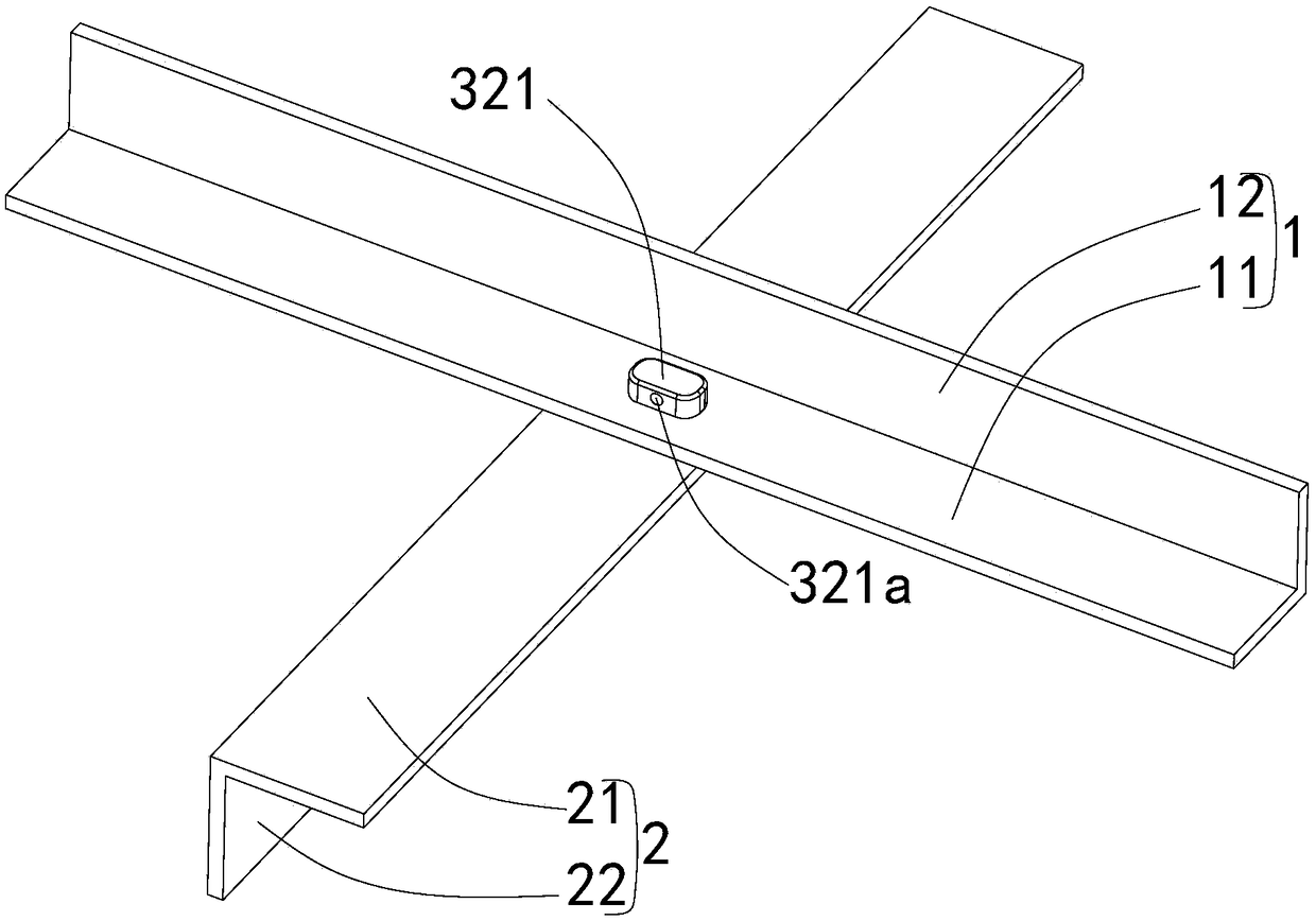
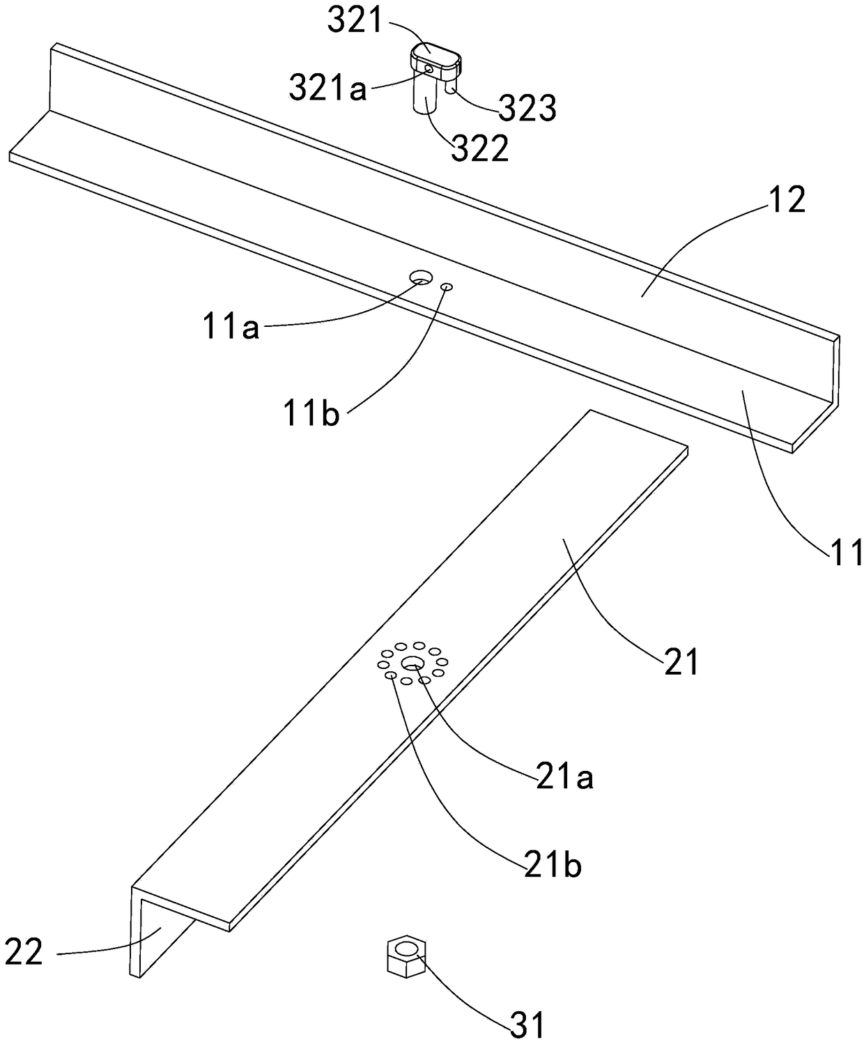
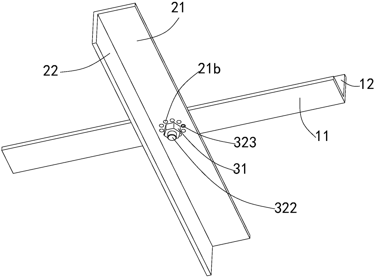
[0011] see Figure 1~4 , This embodiment provides an angle iron cross connection structure, which is characterized in that it includes: a first angle iron 1 , a second angle iron 2 , and a fastening assembly 3 .

[0012] The first angle iron 1 includes a first connecting plate 11 and a second connecting plate 12, the first connecting plate 11 is vertically fixed on one side of the second connecting plate 12; the middle part of the first connecting plate 11 A first through hole 11 a and a second through hole 11 b are provided in the area, and both the first through hole 11 a and the second through ...


PUM


Abstract

The invention discloses an angle iron cross connection structure. The angle iron cross connection structure is characterized by comprising first angle iron, second angle iron and a fastening assembly.The first angle iron comprises a first connection plate and a second connection plate. The middle area of the first connection plate is provided with a first through hole and a second through hole. Both the first through hole and the second through hole penetrate through the first connection plate perpendicularly. The second angle iron comprises a third connection plate and a fourth connection plate. The middle area of the third connection plate is provided with a third through hole and a plurality of fourth through holes. The multiple fourth through holes surround the third through hole in acircular array mode, and thus a plurality of angle locating points are formed. After penetrating through the second through hole, the free end of a locating column can be arranged in any fourth through hole according to the needed cross angle, and thus the included angle between the first angle iron and the second angle iron is fast restrained.

Description

technical field [0001] The invention relates to an angle iron connection structure, in particular to an angle iron cross connection structure. Background technique [0002] In the prior art, the two cross-connected angle irons are usually welded and fixed. When there is a certain angle requirement between the two cross-connected angle irons, the way of welding and fixing is inconvenient to manually restrain the clamping between the two angle irons. horn. Contents of the invention [0003] The purpose of the present invention is to overcome the above-mentioned technical deficiencies, provide a cross connection structure of angle irons, and solve the technical problem in the prior art that it is inconvenient to manually constrain the angle between two angle irons when the angle irons are fixed. [0004] In order to achieve the above technical objectives, the technical solution of the present invention provides an angle iron cross connection structure, which is characterized...

Claims


Application Information

Patent Timeline
IPC IPC(8): F16B7/18
CPCF16B7/18
Inventor 帅田屈金山杨庆宣杜连生
Owner 泰富重工(沙洋)制造有限公司
Features
  • R&D
  • Intellectual Property
  • Life Sciences
  • Materials
  • Tech Scout
  • Unparalleled Data Quality
  • Higher Quality Content
  • 60% Fewer Hallucinations
Learn More