Air flow adjusting structure of air flue and air conditioner
A technology of airflow adjustment and structure adjustment, which is applied in the direction of airflow control components, space heating and ventilation details, noise suppression, etc. Noisy, the effect of promoting the balance of air in and out
- Summary
- Abstract
- Description
- Claims
- Application Information
AI Technical Summary
Problems solved by technology
Method used
Image

Examples
Embodiment 1
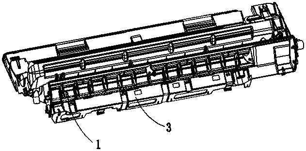
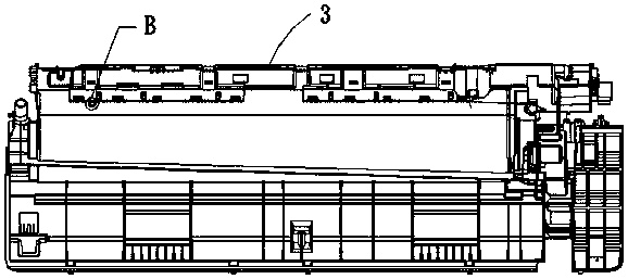
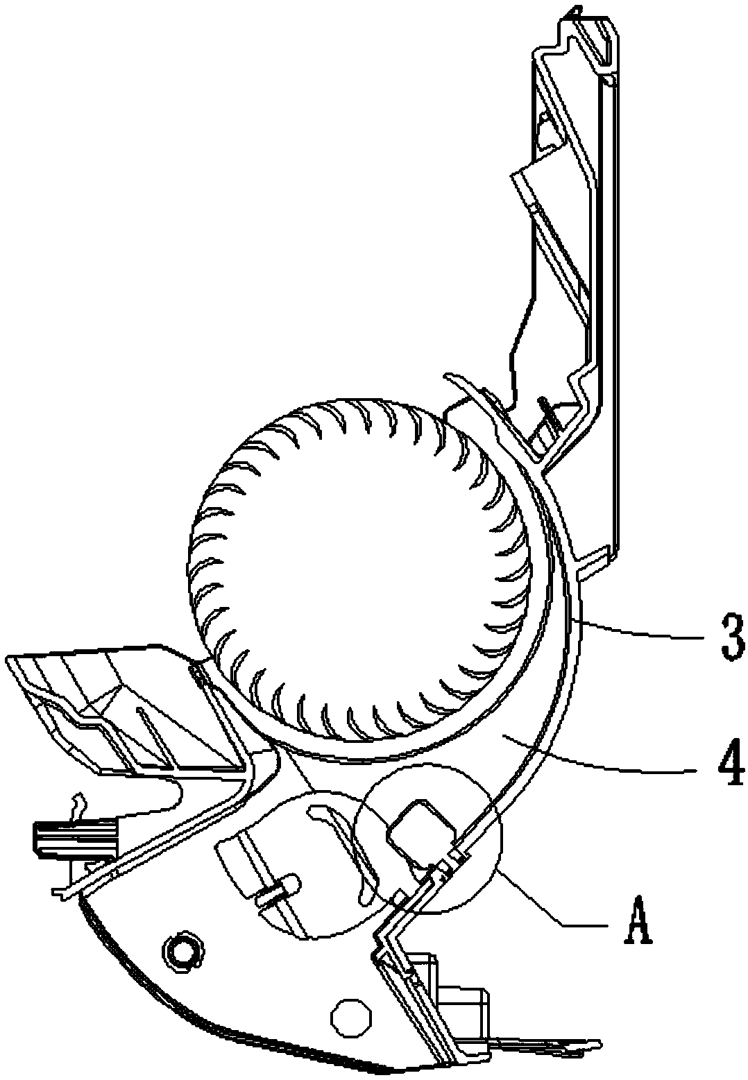
[0039] Such as Figure 1-8 As shown, an airflow regulating structure of an air duct includes an installation hole 2 and an adjustment structure 1, the installation hole 2 is arranged on the base 3, the adjustment structure 1 includes an airflow adjustment part 11 and a shaft part 12, and the airflow adjustment part 11 is located in the air duct 4, the shaft part 12 is rotatably fixed in the installation hole 2; when the air duct 4 is in the air outlet state, the air flow adjustment part 11 changes the air output of the air outlet.
[0040] In this embodiment, the airflow adjustment part 11 is a flat block, and it can also be a block or block of other shapes and thicknesses, such as a triangular block or a rectangular block. The wind direction forms an included angle α, and the included angle α is the rotation angle of the airflow regulating part 11; the shaft part 12 is cylindrical, and the mounting hole 2 is a round hole, thereby facilitating the rotation of the shaft part 12...
Embodiment 2
[0045] Such as figure 1 , 2 , 3, and 4, different from the above-mentioned embodiments, positioning devices for positioning the adjustment structure 1 at different angles are provided between the shaft portion 12 and the installation hole 2 in this embodiment, thus, in the state of air outlet of the air conditioner, Avoid blowing the adjustment structure 1 by the air flow, causing the position of the adjustment structure 1 to change, and causing the air volume of the air inlet and the air outlet to be unbalanced.
[0046] In this embodiment, the positioning device includes a limit groove 6 and a limit bump 5, the limit groove 6 is set in the installation hole 2, and the limit bump 5 is set on the shaft portion 12; the limit groove 6 can be engaged with the limit Protruding point 5, thus, when the shaft portion 12 is located in the mounting hole 2, the limiting groove 6 and the protruding point 5 fit together, similar to the gear structure, the airflow in the air duct 4 is dif...
Embodiment 3
[0051] Such as Figure 4 As shown, different from the above-mentioned embodiment, the installation hole 2 in this embodiment is provided with an annular partition 21 for the shaft portion 12 to pass through, and the annular partition 21 is provided with a limiting groove 6, and along the installation hole 2 In the axial direction, the limiting groove 6 runs through the annular partition 21, so that the limiting groove 6 of the annular partition 21 cooperates with the limiting bump 5 of the shaft part 12 to avoid setting a limiting position directly on the inner wall of the installation hole 2. Groove 6 impels the depth of limiting groove 6 to be too large.
[0052] In this embodiment, one end of the shaft portion 12 is provided with a first protrusion 121, and the outer circumferential surface of the first protrusion 121 is provided with a limiting bump 5, so that when the shaft portion 12 is located in the mounting hole 2, the first The position-limiting protrusion 5 of the ...
PUM
 Abstract
Description
Claims
Application Information
 - R&D
- Intellectual Property
- Life Sciences
- Materials
- Tech Scout
- Unparalleled Data Quality
- Higher Quality Content
- 60% Fewer Hallucinations
Browse by: Latest US Patents, China's latest patents, Technical Efficacy Thesaurus, Application Domain, Technology Topic, Popular Technical Reports.
© 2025 PatSnap. All rights reserved.Legal|Privacy policy|Modern Slavery Act Transparency Statement|Sitemap|About US| Contact US: help@patsnap.com