Amplification augmented reality system for online marking of astigmatism axial position
An astigmatism axial position and augmented reality technology, which is applied in the field of augmented reality technology for real-time indication of corneal astigmatism axial position, can solve the problem that the corneal astigmatism axial position cannot be calibrated online, and achieves the effect of convenient and accurate astigmatism positioning operation.
Active Publication Date: 2019-02-22
WENZHOU MEDICAL UNIV
8 Cites 5 Cited by
AI-Extracted Technical Summary
Problems solved by technology
[0005] In order to overcome the shortcomings of the background technology, the present invention provides an augmented reality system for onli...
Method used
As shown in Figure 1, a kind of augmented reality device system of on-line marking astigmatism axis position comprises micro imaging unit 1, camera unit 2, lighting unit 3, laser pointing unit 4 and control system 5; The micro-imaging unit 1 is used to magnify and image the subject's eye 7 of the subject 6; the illumination unit 3 is used to provide illumination for the micro-imaging unit 1; the laser pointing unit 4 is used to mark online The axial position of the astigmatism of the subject's eye 7 of the inspected object 6; the camera unit 2 is used to capture the image observed in the microscopic imaging unit 1 in real time, and transmit the image to the control system 5; the control system 5. Perform image processing and astigmatism axis calculation on the received image, and simultaneously control the laser pointing unit 4 to track and mark the astigmatism axis of the subject's eye 7 in the microscopic imaging field of view in real time, so that the observation The operator (doctor) 8 can track the axial position synopsically under the microscope, and perform convenient and accurate astigmatism positioning operation.
Below in conjunction with accompanying drawing, the present invention is further described: a kind of augmented reality system of on-line mark astigmatism axis position, comprises: microscopic imaging unit and laser pointing unit, described display imaging unit comprises the eyepiece optical path ...
Abstract
The invention discloses an amplification augmented reality system for online making of an astigmatism axial position. The problem that in the prior art, the cornea astigmatism axial position cannot besubjected to online marking is mainly solved. According to the amplification augmented reality system for online making of the astigmatism axial position, a laser indiction unit performs real-time mark indication on the astigmatism axial position of a detected object in a microscopic imaging view field, an observer can track the axial position under the microscope, and the astigmatism positioningoperation can be performed conveniently and accurately.
Application Domain
Eye surgeryMicroscopes +2
Technology Topic
MicroscopeTime mark +5
Image
Examples
- Experimental program(1)
Example Embodiment
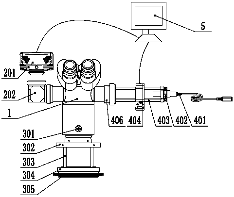
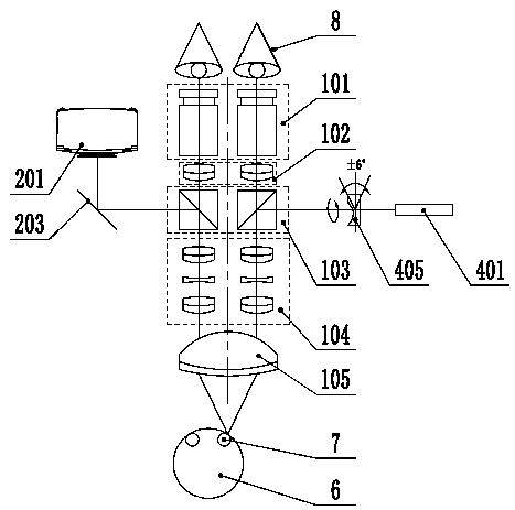
[0022] The present invention will be further explained below with reference to the accompanying drawings: an augmented reality system for marking the axis of astigmatism online, comprising: a microscopic imaging unit and a laser indicating unit, the display imaging unit includes an eyepiece optical path assembly 101, The binocular optical path component 102, the beam splitter prism 103, the variable magnification optical path component 104 and the objective lens 105; the laser indicating unit includes a laser transmitter 401 and a lens 405 that can rotate along its own axis; the laser light emitted by the laser pointer passes through the objective lens It is refracted by the dichroic prism and projected on the eye 7 to be inspected for marking the astigmatism axis of the inspected object. The present invention provides an augmented reality system for marking the axis of astigmatism on-line. A laser indicating unit is used to mark and indicate the axis of astigmatism of an object under inspection in the microscope imaging field of view in real time, so that the observer can view the same under a microscope. Tracking the axis position for convenient and accurate astigmatism positioning operation. As one of the alternatives, the eyepiece optical path assembly includes an eyepiece, the binocular tube optical path assembly includes a binocular tube lens, and the variable magnification optical path assembly includes an upper convex lens, a concave lens, and a lower convex lens.
[0023] In this embodiment, as shown in the figure, it also includes a camera unit 2 for real-time shooting of the image observed in the microscopic imaging unit.
[0024] In this embodiment, as shown in the figure, the camera unit includes a CCD module 201 and a beam splitter 203, and the beam splitter is arranged corresponding to the beam splitter prism.
[0025] In this embodiment, as shown in the figure, it also includes a control system for image processing and astigmatism axis analysis calculations on the received image, and instructs the lens to rotate to perform the astigmatism axis analysis of the object under inspection. Mark.
[0026] In this embodiment, as shown in the figure, it further includes an illumination unit 3 for providing illumination for the microscopic imaging unit.
[0027] In this embodiment, as shown in the figure, the light splitting prism is a light splitting cemented prism.
[0028] In this embodiment, as shown in the figure, both the camera unit and the laser pointer unit are provided with interfaces for communicating with the control system.
[0029] In this embodiment, as shown in the figure, the laser transmitter is a collimated laser diode module 401.
[0030] Such as figure 1 As shown, an augmented reality device system for marking the axis of astigmatism online includes a microscopic imaging unit 1, a camera unit 2, a lighting unit 3, a laser indicating unit 4, and a control system 5; the microscopic imaging unit 1 is used for For magnifying and imaging the inspected eye 7 of the inspected object 6; the illumination unit 3 is used to provide illumination for the microscopic imaging unit 1; the laser indicating unit 4 is used to mark the inspected object 6 online The astigmatism axis position of the eye 7; the camera unit 2 is used to capture the image observed in the microscopic imaging unit 1 in real time, and send the image to the control system 5; the control system 5 pairs all received images The image is processed for image processing and astigmatism axis calculation, and at the same time, the laser indicating unit 4 is controlled to track and indicate the astigmatism axis of the eye 7 in the microscope imaging field of view in real time, so that the observer (doctor) 8 can Simultaneously track the axis position under the microscope for convenient and accurate astigmatism positioning operation.
[0031] Microscopic imaging unit 1, such as figure 2 As shown, it includes an eyepiece optical path assembly 101, a binocular tube optical path assembly 102, a beam splitter cemented prism 103, a variable magnification optical path assembly 104, and an objective lens 105. The light emitted from the inspected eye 7 passes through the objective lens 105, the variable magnification optical path component 104 and the beam splitter cemented prism 103, and is divided into two paths at the splitter cemented prism: one path through the binocular tube optical path component 102 and the eyepiece optical path component 101 for the observer (Doctor) Observation of 8; the other way passes through the spectroscope 203 to the camera unit 2 for imaging and photographing.
[0032] Camera unit 2, combined figure 1 with figure 2 As shown, a CCD module 201, an interface kit 202 and a beam splitter 203 are included. The CCD module 201 generally adopts a full-HD industrial camera for shooting and recording images from the subject's eye 7 through the objective lens 105, the variable magnification optical path component 104, the beam splitter cemented prism 103, and the beam splitter 203. The camera unit 2 is fixedly connected to the micro imaging unit 1 through the interface kit 202, and has a manual focusing function. The captured and recorded images are finally transmitted to the control system 5 through a data line for image processing and astigmatism axis calculation analysis.
[0033] Lighting unit 3, such as figure 1 As shown, a white light source 301, an upper interface 302, a guide rod 303, a lower interface 304, and a circular light source 305 are included. The lighting unit 3 can be used as an optional module. A white light source 301 or a circular ring light source 305 can be selected to provide system lighting. The circular ring light source 305 is fixed on an adjusting frame composed of a lower interface 304, a guide rod 303, and an upper interface 302. The bottom of the microscopic imaging unit 1 is coaxial, and the upper and lower positions can be adjusted by the guide rod 303. The guide rod 303 can also be replaced with a sleeve form with the same function. The white light source 301 includes a halogen lamp including optical fibers, and is generally used for normal illumination of the microscopic imaging unit 1. The circular ring light source 305 can be used as a reference object image for real-time detection and calculation of the astigmatism axis position, and is located on the adjustment frame, which can easily adjust the up and down positions.
[0034] Laser indicating unit 4, combined figure 1 with figure 2 As shown, it includes a collimating laser diode module 401, an adapter assembly 402, a support rod 403, a rotating mount 404, a lens 405, and an interface assembly 406. The collimated laser diode module 401 includes a collimated laser diode and power supply accessories for the laser module. The laser power is adjustable and far lower than the laser damage threshold of the object 6 and the observer (doctor) 8 (here, the laser power Adjustable range: 0~5mW. Generally, the laser power from a laser is constant, such as a 4mW power laser, and we adjust the attenuation degree of the laser in the system, so that the attenuated laser power before entering the eye is much lower than The laser damage threshold of the human eye--below -1mw/cm^2) to ensure the safe operation of the system. The adapter assembly 402 mounts the laser diode housing in the adjustment frame, and can provide a certain angle (±6° in the example) pitch and yaw position adjustment control through the fine adjustment screw on the adapter assembly. The lens 405 is installed in the hole of the rotating mount 404 through a snap ring. The rotating mount 404 has the characteristics of full 360° bidirectional rotation and unidirectional repeatability of ±60 microradians, and has a built-in controller and high A stepping motor with a speed turbine is used to precisely rotate and control the lens 405. As one of the alternatives, the rotary mounting seat can adopt the rotary mounting seat K10CR1(/M) type from THORLABS.
[0035] Further, the control system 5 can be connected through a data cable, and the control system 5 can perform automatic rotation adjustment, or can directly perform manual rotation adjustment through the upper manual knob. The adapter assembly 402, the rotating mounting seat 404, and the interface assembly 406 are connected and fixed by the support rod 403, and the distance between the three can also be adjusted by the support rod 403. The other end of the interface assembly 406 is connected with the micro imaging unit through a thread.
[0036] The laser with a specific power output from the collimated laser diode module 401 enters the subject's eye 7 through the lens 405, the beam splitter cemented prism 103, the variable magnification optical path component 104 and the objective lens 105 to produce an axial laser marking, and then passes through the objective lens 105 and the variable magnification optical path through reflection The component 104, the spectroscopic cemented prism 103, the binocular tube optical path component 102, and the eyepiece optical path component 101 reach the observation field of view of the observer (doctor) 8. The laser marking of the axis position can be adjusted to specify the position and size through the rotating mount 404 and the adapter assembly 402.
[0037] In the foregoing embodiment, the optical elements in the optical path assembly are all coated to ensure the personal safety of the inspected object 6 and the observer 8 to the laser-indicated axis marking line.
[0038] Such as image 3 As shown, 9 is the implanted intraocular lens, 10 is the surgical incision position, 13 is the reference horizontal position line, 12 is the axis mark of the implanted intraocular lens, and 11 is the corneal astigmatism axis introduced by the laser indicating unit 4 In the cataract surgery process, the intraocular lens axis mark 12 is overlapped with the corneal astigmatism axis mark line 11 to complete the corneal astigmatism correction. The indicating marking line 11 can realize the adjustment of different indicating sizes, directions and positions by adjusting the laser indicating unit 4.
[0039] It should be pointed out that in the embodiment, the left side is the camera unit 2 and the right side is the laser pointer unit 4. Actually, the positions can be exchanged as needed, without affecting the performance of the overall system. The present invention is an augmented reality system that performs online marking on the basis of a microscopic imaging system. In the embodiment, the camera unit 2, the lighting unit 3, the laser indicating unit 4 and the control system 5 can be combined to realize the inspection of the eye 7 The integrated function of real-time automatic calculation and analysis of the corneal astigmatism axis and online marking can also be removed from the camera unit 2 and the control system 5 and transformed into a single function of online manual adjustment of markings.
[0040] In the description of the present invention, it should be understood that the terms "length", "width", "upper", "lower", "front", "rear", "left", "right", "vertical", The orientation or positional relationship indicated by "horizontal", "top", "bottom", "inner", "outer", etc. is based on the orientation or positional relationship shown in the drawings, and is only for the convenience of describing the present invention and simplifying the description, not It indicates or implies that the pointed device or element must have a specific orientation, be configured and operated in a specific orientation, and therefore cannot be understood as a limitation of the present invention.
[0041] In addition, the terms "first" and "second" are only used for descriptive purposes, and cannot be understood as indicating or implying relative importance or implicitly indicating the number of indicated technical features. Thus, the features defined with "first" and "second" may explicitly or implicitly include one or more of these features. In the description of the present invention, "plurality" means two or more than two, unless specifically defined otherwise.
[0042] The embodiments described with reference to the drawings are exemplary, and are intended to explain the present invention, but should not be construed as limiting the present invention. The embodiments should not be regarded as limiting the present invention, but any improvement made based on the spirit of the present invention should fall within the protection scope of the present invention.
PUM


Description & Claims & Application Information
We can also present the details of the Description, Claims and Application information to help users get a comprehensive understanding of the technical details of the patent, such as background art, summary of invention, brief description of drawings, description of embodiments, and other original content. On the other hand, users can also determine the specific scope of protection of the technology through the list of claims; as well as understand the changes in the life cycle of the technology with the presentation of the patent timeline. Login to view more.