Radar tachymeter capable of automatically adjusting angle compensation

A radar speedometer and angle compensation technology, which is applied in the field of radar speedometers, can solve the problems of inconvenient angle adjustment, poor adaptability, fixed structure, etc., and achieves the effect of strong practicability and improved speed measurement range.

Inactive Publication Date: 2019-02-22
杭州来涞科技有限公司
5 Cites 5 Cited by

AI-Extracted Technical Summary

Problems solved by technology

[0002] In the prior art, the structure of the radar speedometer after installation is relatively fixed, it is not convenient to adjust the angle according to the needs, realize th...

Method used

Adjustment assembly 5 comprises installation collar 51, recessed platform 52, rack 53, gear one 54, opening 55, outer ring gear 56, connecting frame 57 and gear two 58, and installation collar 51 is sleeved on moving rod 4 annular On the side, the concave table 52 is processed on the upper end of the annular side of the moving rod 4 on the right side of the installation ring sleeve 51, the rack 53 is fixed on the upper end surface of the concave table 52, the opening 55 is opened on the upper end of the support plate two 3, and the opening 55 is provided with a rotating shaft inside. And the rear end of the rotating shaft is along to the rear side of the support plate 2, the gear 54 is installed on the annular side of the rotating shaft, and the gear 54 is meshed with the rack 53, and the outer ring gear 56 is fixed ...

Abstract

The invention provides a radar tachymeter capable of automatically adjusting angle compensation. The radar tachymeter comprises a bottom plate, a support plate I, a support plate II, a moving rod, anadjustment assembly and a radar tachymeter body. The support plate I is installed at the left of the upper end surface of the bottom plate; the support plate II is installed at the right of the upperend surface of the bottom plate; and the left end of the moving rod is installed at the upper end of the support plate I and the right end of the moving rod is installed at the upper end of the support plate II. The adjustment assembly is arranged at the annular side of the moving rod. The radar tachymeter body is installed at the upper end of the adjustment assembly. On the basis of the design, micro tuning of the angle and position of the radar tachymeter after installation is realized. Moreover, the radar tachymeter having a simple structure is convenient to use and operate; the micro tuning of the angle and position is realized; and the adaptability is high.

Application Domain

Stands/trestlesRadio wave reradiation/reflection

Technology Topic

EngineeringRadar +1

Image

  • Radar tachymeter capable of automatically adjusting angle compensation
  • Radar tachymeter capable of automatically adjusting angle compensation
  • Radar tachymeter capable of automatically adjusting angle compensation

Examples

  • Experimental program(1)

Example Embodiment

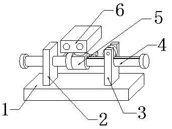
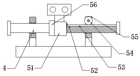
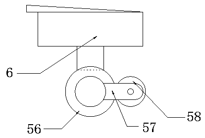
[0029] Specific implementation method: before use, the staff connects the small motor 1 and the small motor 2 with the external power supply. During use, the staff adjusts the radar speedometer body 6 according to the needs. One and the circuit between the small motor two and the external power supply are connected, the small motor one drives the rotating shaft one to rotate, the rotating shaft one rotates to drive the gear one 54 to rotate, the gear one 54 rotates to drive the rack 53 to move, and the rack 53 moves to drive the moving bar 4 moves, and the movement of the moving rod 4 drives the installation ring 51 to move, thereby driving the radar speedometer body 6 to move. When the radar speedometer body 6 moves to a predetermined position, the small motor 1 stops running, and the small motor 2 moves to drive the rotating shaft 2 Rotate, rotating shaft 2 drives gear 2 58 to rotate, gear 2 58 rotates to drive outer ring gear 56 to rotate, and outer ring gear 56 rotates to drive mounting ring sleeve 51 to rotate around moving rod 4, thereby drives radar speedometer body 6 to rotate, when rotating When the predetermined angle is reached, the small motor can be stopped, so that the main body of the radar detector can be realized, and the operation is simple. .

PUM

no PUM

Description & Claims & Application Information

We can also present the details of the Description, Claims and Application information to help users get a comprehensive understanding of the technical details of the patent, such as background art, summary of invention, brief description of drawings, description of embodiments, and other original content. On the other hand, users can also determine the specific scope of protection of the technology through the list of claims; as well as understand the changes in the life cycle of the technology with the presentation of the patent timeline. Login to view more.

Similar technology patents

Large-scale bi-dimensional fractured rock mass shearing seepage meter

ActiveCN104865177AFully functionalPractical
Owner:CHONGQING UNIV

Shear-fork type variable-pitch mechanical arm

InactiveCN104429247ASimple structurePractical
Owner:迁西县板栗产业研究发展中心

Speed measurement method applied to radar, speed measurement device and electronic equipment

ActiveCN108680918AIncrease speed rangeMeet application needs
Owner:WHST CO LTD

Classification and recommendation of technical efficacy words

  • Practical
  • Increase speed range

User behavior self-learning air conditioning system and control method thereof

ActiveCN105318499AConvenience and good experiencePractical
Owner:GD MIDEA AIR-CONDITIONING EQUIP CO LTD +1

Intelligent grid comprehensive evaluating system based on analytic hierarchy process and fuzzy comprehensive evaluation

InactiveCN102663508ADemonstrate economic and social benefitsPractical
Owner:NORTHEAST POWER SCI RES INSTITUTION +2

Management system based on shared bicycle and method thereof

PendingCN107016594AReduce maintenance and management costsPractical
Owner:广东小强信息科技有限公司

Speed measurement method applied to radar, speed measurement device and electronic equipment

ActiveCN108680918AIncrease speed rangeMeet application needs
Owner:WHST CO LTD
Why Eureka
Try Eureka