Speed measurement method applied to radar, speed measurement device and electronic equipment

A radar and speed measurement technology, applied in the field of radar, can solve the problems of radar speed measurement range limitation, spectrum overlap, radar target speed measurement confusion, etc., to meet application requirements and improve the effect of speed measurement range

Active Publication Date: 2018-10-19
WHST CO LTD
3 Cites 9 Cited by

AI-Extracted Technical Summary

Problems solved by technology

[0003] However, the radar system collects data signals through an analog-to-digital converter. Due to the limitation of the sampling rate of the analog-to-digital converter, when the sampling interval is too wide, it will cause sp...

Abstract

The invention is suitable for the radar technology field and provides a speed measurement method applied to a radar, a speed measurement device, electronic equipment and a computer readable storage medium. The speed measurement method comprises the following steps of based on the track information of a target, calculating the distance change rate of the target; based on the distance change rate, calculating the speed blur multiple of the speed measurement value of the target; and according to the speed blur multiple, carrying out speed deblur and acquiring the real speed of the target. In theinvention, the speed measurement range of the radar can be effectively increased and the application demand of a vehicle-borne radar is satisfied.

Application Domain

Technology Topic

Image

  • Speed measurement method applied to radar, speed measurement device and electronic equipment
  • Speed measurement method applied to radar, speed measurement device and electronic equipment
  • Speed measurement method applied to radar, speed measurement device and electronic equipment

Examples

  • Experimental program(1)

Example Embodiment

[0045] In the following description, for the purpose of illustration rather than limitation, specific details such as a specific system structure and technology are proposed for a thorough understanding of the embodiments of the present invention. However, it should be clear to those skilled in the art that the present invention can also be implemented in other embodiments without these specific details. In other cases, detailed descriptions of well-known systems, devices, circuits, and methods are omitted to avoid unnecessary details from obstructing the description of the present invention.
[0046] In order to make the objectives, technical solutions, and advantages of the present invention clearer, the following will illustrate with specific embodiments in conjunction with the accompanying drawings.
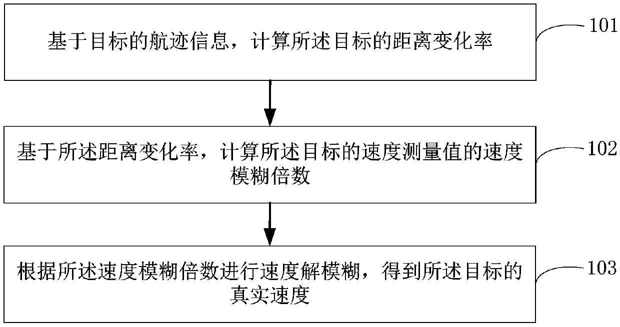
[0047] See figure 1 , Which shows the implementation flowchart of the speed measurement method applied to radar according to the embodiment of the present invention, and the details are as follows:
[0048] Step 101: Calculate the distance change rate of the target based on the track information of the target.
[0049] In the embodiments of the present invention, a target refers to anything that the radar is interested in its state. For example, when applied to a vehicle-mounted radar, the vehicle-mounted radar will track and measure things within a certain range near the vehicle. The state of the target is a variable. Including components such as position, velocity, acceleration, etc., these components are all functions that change with time and follow the law of dynamics. The embodiments of the present invention are aimed at the velocity variable of the target.
[0050] In the embodiment of the present invention, the track refers to the sequence of measurement values ​​derived from the same target determined by the radar. Specifically, the radar sends an electromagnetic wave signal, and receives the returned electromagnetic wave signal, and the returned electromagnetic wave signal is first input to the signal processor for processing. Process to form the measured value point trace data, and then perform gate judgment and data association on the measured value point trace data, and then obtain the track information of the target, where the target refers to the same target.
[0051] In the embodiment of the present invention, the measured value refers to the observations related to the target state sent from the radar sensor. These observations are generally contaminated by noise and may have errors or ambiguities.
[0052] It should be noted that the target's track information can reflect the change of the target's position, and the position change can reflect the change of the target's distance from the radar. Therefore, based on the target's position at different times, the target's distance change rate can be calculated .
[0053] Optionally, in step 101, the distance change rate of the target can be calculated according to a preset first formula, and the first formula is:
[0054]
[0055] Among them, the Indicates the rate of change of the distance of the target, the R n Means t n The position of the target at the moment, the R m Means t m The location of the target at the moment.
[0056] In one embodiment, t n Time represents the current time, and t m Time represents the moment before the current moment, then, calculated according to the first formula above It can represent the target's distance change rate at the current moment relative to the previous moment.
[0057] Optionally, the implementation process of the foregoing step 101 may further include the following steps:
[0058] Step A: Based on the track information of the target, calculate the distance prediction value of the target under preset different speed blur values ​​at the current moment.
[0059] According to the Nyquist sampling theorem, the sampled data (measured value) of the radar has a range. For example, when the radar speed measurement, the speed measurement value will not exceed a range. If the actual speed (true speed) of the target is in the radius If the upward projection component exceeds this range, velocity ambiguity will occur, that is, the radial velocity observed by the radar is not the actual radial velocity of the target. Here, the maximum radial velocity that the radar can obtain is called the maximum unambiguous velocity . The actual radial velocity of the target and the observed radial velocity satisfy a certain relationship. Different sampling frequencies can correspond to different velocity blur values. In the embodiment of the present invention, the three velocity blurs of "+1, 0, -1" The speed measurement results under the value are processed, which can increase the speed measurement range of the radar by three times. Among them, the speed fuzzy value of "0" means that the speed measurement result does not produce speed ambiguity, and the speed measurement value in this situation reflects the true speed of the target to a certain extent (excluding interference); the speed fuzzy value of "+1" means speed measurement As a result, speed blur is generated, and the speed measurement result needs to be corrected by adding 1 times the maximum unambiguous speed; the speed blur value "-1" means that the speed measurement result has speed blur, and the speed measurement result needs to be reduced Go to 1 times the maximum unblurring speed for correction.
[0060] Exemplarily, assuming that the actual speed range of the radar is -50m/s to +50m/s, its maximum unambiguous speed is 100m/s; if the real speed of the target is +10m/s, it is due to the actual speed of the radar Within the range, the radar will not produce velocity ambiguity in its velocity measurement. The velocity measurement result is +10m/s, which is the measurement result under the "0" velocity ambiguity value; when the actual speed of the target is 110m/s, The speed measurement of the radar will produce speed ambiguity, and the speed measurement result is also +10m/s. This situation belongs to the measurement result under the "+1" velocity ambiguity value; when the actual speed of the target is -90m/s, the radar Its speed measurement will produce speed blur, and its speed measurement result is also +10m/s. This situation belongs to the measurement result under the "-1" speed blur value.
[0061] Since the process of acquiring the track information of the target needs to filter the state variables of the target through a recursive linear filter, in the embodiment of the present invention, a Kalman filter is used to achieve the track filtering of the target. The state transition equation and observation equation of the Kalman filter are both statistical models. The state transition equation can describe the change in the position (distance) of the target over time, that is, the state prediction process. The observation equation can give the observed value of the target and The relationship between state variables is the state update process.
[0062] In the embodiment of the present invention, in the state prediction process of the Kalman filter, the distance prediction results under the conditions of three velocities (velocity ambiguity values ​​+1, 0, -1) are calculated, so that the distance measurement value of the target by the radar is calculated. Corrections and updates.
[0063] Step B: Associating the distance measurement value of the target with the distance prediction value at the current moment to determine the distance prediction value corresponding to the distance measurement value.
[0064] Since three distance prediction results are calculated in step A, the distance measurement value at the current time needs to be associated with one of the three distance prediction results. In the embodiment of the present invention, the detection result at the current time and the track at the previous time In the data association process of the filtering result, the distance prediction value calculated by the three speeds is used for distance association to determine the distance prediction result corresponding to the distance measurement value at the current moment.
[0065] In the embodiment of the present invention, the nearest neighbor data association algorithm may be used to realize the distance association between the distance measurement value at the current moment and the distance prediction value calculated by the three speeds.
[0066] Step C: Correct the distance measurement value by determining the distance prediction value corresponding to the distance measurement value to obtain the true distance value of the target at the current moment;
[0067] In the embodiment of the present invention, through distance association, the distance prediction value corresponding to the distance measurement value can be determined, so as to realize the correction of the distance measurement value of the target by the radar at the current moment, so that the true distance of the target at the current moment can be obtained, and The track information of the target can be updated according to the true distance of the target at the current moment.
[0068] Step D: Calculate the distance change rate of the target based on the true distance value of the target at the current moment and the true distance value of the target at the previous moment.
[0069] In the embodiment of the present invention, the actual distance change rate of the target at the current moment can be determined through the true distance of the target at the current moment and the true distance of the target at the previous moment. Among them, the true distance value of the target at the previous moment can be reflected in the target's track information.
[0070] It should be noted that, in the embodiment of the present invention, the true distance value is relative to the distance measurement value of the radar to the target, and refers to the actual distance after the radar measurement value of the target is updated and corrected.
[0071] Optionally, after obtaining the true distance value of the target at the current moment, the method further includes: updating the track information of the target by the true distance value of the target at the current moment.
[0072] In the embodiment of the present invention, during the state update process of the Kalman filter, it is necessary to calculate the state optimization results under the conditions of the above three speeds (velocity ambiguity value +1, 0, -1), so as to perform the target track information Update so that the system can predict the state of the target at the next moment based on the track information.
[0073] Step 102: Calculate the speed fuzzy multiple of the measured speed value of the target based on the distance change rate;
[0074] In the embodiment of the present invention, after the target's range change rate is obtained, according to the target's range change rate, the velocity ambiguity multiple of the speed measurement value of the radar to the target at the current moment can be calculated, that is, the speed of the radar to the target at the current moment is determined Whether the measured value has a speed blur, if it has a speed blur, you can determine the speed blur multiple it produces.
[0075] Optionally, the above step 102 can be implemented in the following ways:
[0076] Calculate the speed fuzzy multiple of the measured speed value of the target according to a preset second formula, and the second formula is:
[0077]
[0078] Wherein, the N represents the velocity fuzzy multiple of the measured velocity of the target, the N is an integer, and the Indicates the rate of change of the distance of the target, the v 0 Indicates the measured speed of the target, the v unambi Indicates the maximum unambiguous speed of the radar.
[0079] In the embodiment of the present invention, the maximum unambiguity speed of the radar is related to the wavelength and pulse repetition frequency of the radar. Specifically, the maximum unambiguity speed of the radar v unambi And radar wavelength λ, pulse repetition frequency f PR The relationship is as follows:
[0080]
[0081] It should be noted that when the target's current distance change rate is equal to the target's current speed measurement value, it means that the current speed measurement value does not have speed ambiguity, that is, the speed of the target speed measurement value in this situation The blur factor is 0.
[0082] Step 103: Perform speed defuzzification according to the speed blur multiple to obtain the true speed of the target.
[0083] In the embodiment of the present invention, after determining the velocity ambiguity multiple of the speed measurement value of the radar target at the current moment, the velocity ambiguity multiple of the velocity measurement value of the radar can be used to realize the defuzzification of the velocity measurement value of the radar to the target, thereby obtaining the true target speed.
[0084] In the embodiment of the present invention, the true speed represents the actual speed of the target, that is, the speed measurement value of the radar on the target under the condition that no speed ambiguity occurs, or when the speed measurement value of the radar on the target produces speed ambiguity, The speed measurement value of the radar is corrected to the target speed.
[0085] Optionally, the foregoing step 103 can be implemented in the following manner:
[0086] Perform velocity defuzzification according to a preset third formula to obtain the true velocity of the target, and the third formula is:
[0087] v′=N×v unambi +v 0
[0088] Wherein, the v'represents the true speed of the target, the N represents the speed ambiguity multiple of the measured speed of the target, the N is an integer, and the v unambi Represents the maximum unambiguous speed of the radar, the v 0 Indicates the measured speed of the target.
[0089] It can be seen from the above that the present invention calculates the target's distance change rate based on the target's track information; since the target's track information reflects the target's trajectory, the target's distance change rate calculated based on the track information To a certain extent, it can reflect whether the speed measurement value of the radar on the target is the value after the speed ambiguity; then, based on the distance change rate, the speed ambiguity multiple of the target speed measurement value can be calculated; The radar performs speed defuzzification on the speed measurement value of the target, so that the true speed of the target can be obtained; therefore, the present invention can realize the conversion of the speed measurement value after the speed ambiguity is generated into the true speed value of the target, thereby effectively improving the radar performance The speed range meets the application requirements of vehicle radar.
[0090] It should be understood that the size of the sequence number of each step in the foregoing embodiment does not mean the order of execution, and the execution sequence of each process should be determined by its function and internal logic, and should not constitute any limitation on the implementation process of the embodiment of the present invention.
[0091] The following are device embodiments of the present invention. For details that are not described in detail, reference may be made to the corresponding method embodiments above.
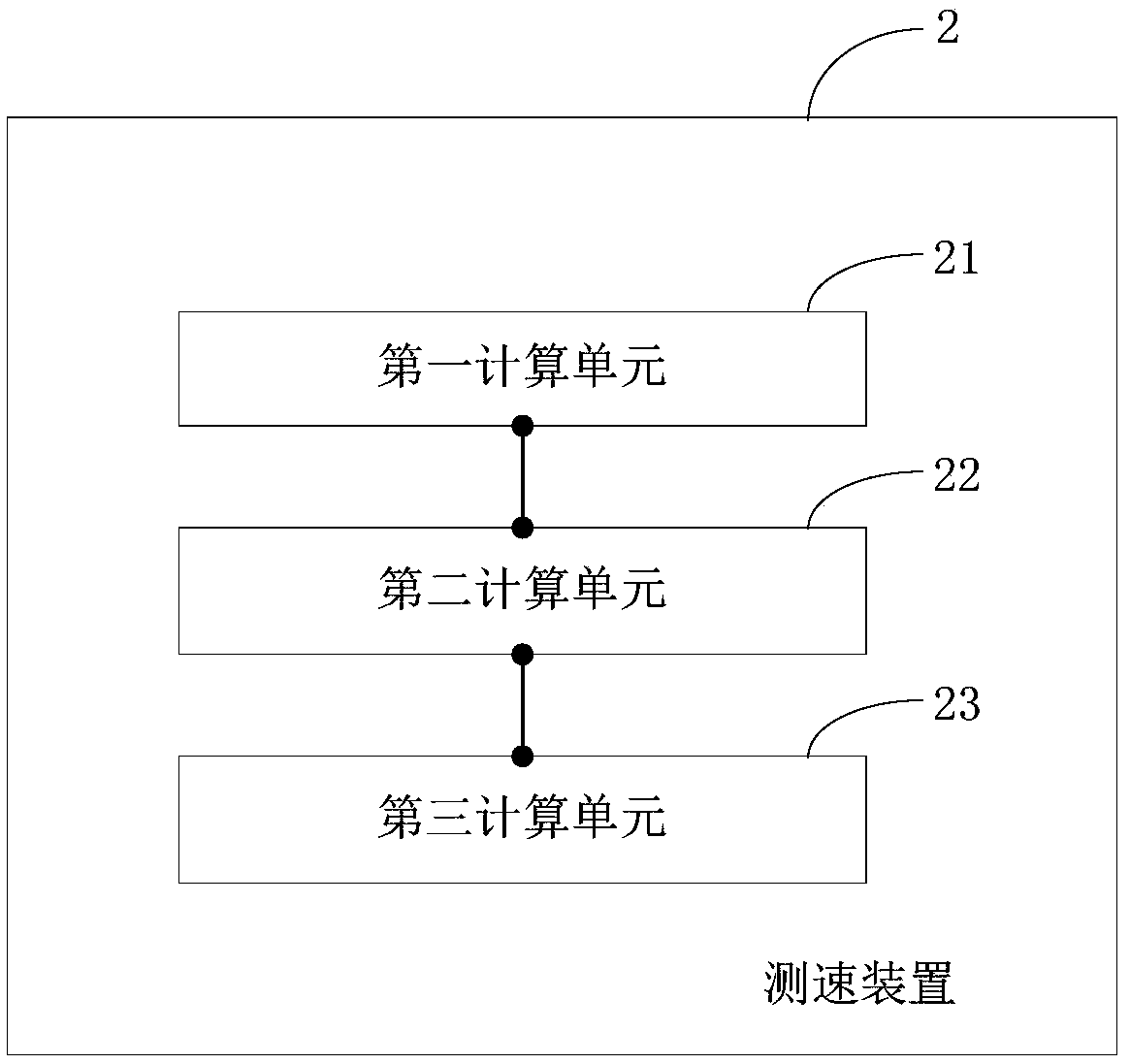
[0092] figure 2 It shows a schematic structural diagram of a speed measuring device applied to a radar according to an embodiment of the present invention. For ease of description, only parts related to the embodiment of the present invention are shown, which are described in detail as follows:
[0093] Such as figure 2 As shown, the speed measuring device 2 includes: a first calculation unit 21, a second calculation unit 22, and a third calculation unit 23.
[0094] The first calculation unit 21 is configured to calculate the distance change rate of the target based on the track information of the target;
[0095] The second calculation unit 22 is configured to calculate the speed fuzzy multiple of the measured speed value of the target based on the distance change rate of the target calculated by the first calculation unit 21;
[0096] The third calculation unit 23 is configured to perform speed defuzzification according to the speed blur multiple calculated by the second calculation unit 22 to obtain the true speed of the target.
[0097] Optionally, the speed measuring device 2 further includes:
[0098] The fourth calculation unit is used to calculate the distance prediction value of the target under preset different speed blur values ​​at the current moment based on the track information of the target;
[0099] A distance association unit, configured to associate the distance measurement value of the target at the current moment with the distance prediction value calculated by the fourth calculation unit to determine the distance prediction value corresponding to the distance measurement value;
[0100] A correction unit, configured to correct the distance measurement value by using the distance prediction value corresponding to the distance measurement value determined by the distance association unit to obtain the true distance value of the target at the current moment;
[0101] The first calculation unit 21 is specifically configured to calculate the distance change rate of the target based on the true distance value of the target at the current moment obtained by the correction unit and the true distance value of the target at the previous moment, wherein: The true distance value of the target at the previous moment is obtained based on the track information of the target.
[0102] Optionally, the speed measurement device 2 further includes an update unit for updating the track information of the target by using the true distance value of the target at the current time after obtaining the true distance value of the target at the current time.
[0103] Optionally, the first calculation unit 21 is specifically configured to calculate the distance change rate of the target according to a preset first formula, and the first formula is:
[0104]
[0105] Among them, the Indicates the rate of change of the distance of the target, the R n Means t n The position of the target at the moment, the R m Means t m The location of the target at the moment.
[0106] Optionally, the second calculation unit 22 is specifically configured to calculate the speed fuzzy multiple of the measured speed value of the target according to a preset second formula, and the second formula is:
[0107]
[0108] Wherein, the N represents the velocity fuzzy multiple of the measured velocity of the target, the N is an integer, and the Indicates the rate of change of the distance of the target, the v 0 Indicates the measured speed of the target, the v unambi Indicates the maximum unambiguous speed of the radar.
[0109] Optionally, the third calculation unit 23 is specifically configured to perform speed defuzzification according to a preset third formula to obtain the true speed of the target, and the third formula is:
[0110] v′=N×v unambi +v 0
[0111] Wherein, the v'represents the true speed of the target, the N represents the speed ambiguity multiple of the measured speed of the target, the N is an integer, and the v unambi Represents the maximum unambiguous speed of the radar, the v 0 Indicates the measured speed of the target.
[0112] It can be seen from the above that the present invention calculates the target's distance change rate based on the target's track information; since the target's track information reflects the target's trajectory, the target's distance change rate calculated based on the track information To a certain extent, it can reflect whether the speed measurement value of the radar on the target is the value after the speed ambiguity; then, based on the distance change rate, the speed ambiguity multiple of the target speed measurement value can be calculated; The radar performs speed defuzzification on the speed measurement value of the target, so that the true speed of the target can be obtained; therefore, the present invention can realize the conversion of the speed measurement value after the speed ambiguity is generated into the true speed value of the target, thereby effectively improving the radar performance The speed range meets the application requirements of vehicle radar.
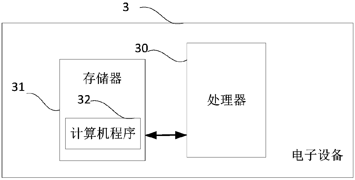
[0113] image 3 It is a schematic diagram of an electronic device provided by an embodiment of the present invention. Such as image 3 As shown, the electronic device 3 of this embodiment includes a processor 30, a memory 31, and a computer program 32 stored in the memory 31 and running on the processor 30. When the processor 30 executes the computer program 32, the steps in the above embodiments of the speed measurement method applied to radar are implemented, for example figure 1 Steps 101 to 103 are shown. Alternatively, when the processor 30 executes the computer program 32, the functions of the modules/units in the foregoing device embodiments are implemented, for example figure 2 The functions of units 21 to 23 are shown.
[0114] Exemplarily, the computer program 32 may be divided into one or more modules/units, and the one or more modules/units are stored in the memory 31 and executed by the processor 30 to complete this invention. The one or more modules/units may be a series of computer program instruction segments capable of completing specific functions, and the instruction segments are used to describe the execution process of the computer program 32 in the electronic device 3. For example, the computer program 32 may be divided into a first calculation unit, a second calculation unit, and a third calculation unit. The specific functions of each unit are as follows:
[0115] The first calculation unit is configured to calculate the target's distance change rate based on the target's track information;
[0116] The second calculation unit is configured to calculate the speed blur multiple of the measured speed value of the target based on the distance change rate of the target calculated by the first calculation unit;
[0117] The third calculation unit is used to perform speed defuzzification according to the speed blur multiple to obtain the true speed of the target.
[0118] The electronic device 3 may be a computing device such as a desktop computer, a notebook, a palmtop computer, and a cloud server. The electronic device may include, but is not limited to, a processor 30 and a memory 31. Those skilled in the art can understand, image 3 It is only an example of the electronic device 3, and does not constitute a limitation on the electronic device 3. It may include more or fewer components than shown in the figure, or a combination of certain components, or different components. For example, the electronic device may also include Input and output equipment, network access equipment, bus, etc.
[0119] The so-called processor 30 may be a central processing unit (Central Processing Unit, CPU), other general-purpose processors, digital signal processors (Digital Signal Processor, DSP), application specific integrated circuits (Application Specific Integrated Circuit, ASIC), Field-Programmable Gate Array (FPGA) or other programmable logic devices, discrete gates or transistor logic devices, discrete hardware components, etc. The general-purpose processor may be a microprocessor or the processor may also be any conventional processor or the like.
[0120] The memory 31 may be an internal storage unit of the electronic device 3, such as a hard disk or a memory of the electronic device 3. The memory 31 may also be an external storage device of the electronic device 3, such as a plug-in hard disk, a smart memory card (Smart Media Card, SMC), and a secure digital (Secure Digital, SD) equipped on the electronic device 3. Card, Flash Card, etc. Further, the memory 31 may also include both an internal storage unit of the electronic device 3 and an external storage device. The memory 31 is used to store the computer program and other programs and data required by the electronic device. The memory 31 can also be used to temporarily store data that has been output or will be output.
[0121] Those skilled in the art can clearly understand that for the convenience and conciseness of the description, only the division of the above-mentioned functional units and modules is used as an example. In practical applications, the above-mentioned functions can be allocated to different functional units and modules as required. Module completion means dividing the internal structure of the device into different functional units or modules to complete all or part of the functions described above. The functional units and modules in the embodiments can be integrated into one processing unit, or each unit can exist alone physically, or two or more units can be integrated into one unit. The above-mentioned integrated units can be hardware-based Form realization can also be realized in the form of software functional unit. In addition, the specific names of the functional units and modules are only for the convenience of distinguishing each other, and are not used to limit the protection scope of the present application. For the specific working process of the units and modules in the foregoing system, reference may be made to the corresponding process in the foregoing method embodiment, which is not repeated here.
[0122] In the above-mentioned embodiments, the description of each embodiment has its own emphasis. For parts that are not detailed or recorded in an embodiment, reference may be made to related descriptions of other embodiments.
[0123] A person of ordinary skill in the art may realize that the units and algorithm steps of the examples described in combination with the embodiments disclosed herein can be implemented by electronic hardware, or a combination of computer software and electronic hardware. Whether these functions are executed by hardware or software depends on the specific application and design constraints of the technical solution. Professionals and technicians can use different methods for each specific application to implement the described functions, but such implementation should not be considered as going beyond the scope of the present invention.
[0124] In the embodiments provided by the present invention, it should be understood that the disclosed device/electronic device and method may be implemented in other ways. For example, the device/electronic device embodiments described above are only illustrative. For example, the division of the modules or units is only a logical function division, and there may be other divisions in actual implementation, such as multiple units. Or components can be combined or integrated into another system, or some features can be omitted or not implemented. In addition, the displayed or discussed mutual coupling or direct coupling or communication connection may be indirect coupling or communication connection through some interfaces, devices or units, and may be in electrical, mechanical or other forms.
[0125] The units described as separate components may or may not be physically separated, and the components displayed as units may or may not be physical units, that is, they may be located in one place, or they may be distributed on multiple network units. Some or all of the units may be selected according to actual needs to achieve the objectives of the solutions of the embodiments.
[0126] In addition, the functional units in the various embodiments of the present invention may be integrated into one processing unit, or each unit may exist alone physically, or two or more units may be integrated into one unit. The above-mentioned integrated unit can be realized in the form of hardware or software functional unit.
[0127] If the integrated module/unit is implemented in the form of a software functional unit and sold or used as an independent product, it can be stored in a computer readable storage medium. Based on this understanding, the present invention implements all or part of the processes in the above-mentioned embodiments and methods, and can also be completed by instructing relevant hardware through a computer program. The computer program can be stored in a computer-readable storage medium. When the program is executed by the processor, it can implement the steps of the foregoing method embodiments. Wherein, the computer program includes computer program code, and the computer program code may be in the form of source code, object code, executable file, or some intermediate forms. The computer-readable medium may include: any entity or device capable of carrying the computer program code, recording medium, U disk, mobile hard disk, magnetic disk, optical disk, computer memory, read-only memory (ROM, Read-Only Memory) , Random Access Memory (RAM, Random Access Memory), electrical carrier signal, telecommunications signal, and software distribution media. It should be noted that the content contained in the computer-readable medium can be appropriately added or deleted according to the requirements of the legislation and patent practice in the jurisdiction. For example, in some jurisdictions, according to the legislation and patent practice, the computer-readable medium Does not include electrical carrier signals and telecommunication signals.
[0128] The above-mentioned embodiments are only used to illustrate the technical solutions of the present invention, but not to limit them; although the present invention has been described in detail with reference to the foregoing embodiments, those of ordinary skill in the art should understand that it can still implement the foregoing The technical solutions recorded in the examples are modified, or some of the technical features are equivalently replaced; these modifications or replacements do not cause the essence of the corresponding technical solutions to deviate from the spirit and scope of the technical solutions of the embodiments of the present invention, and should be included in Within the protection scope of the present invention.

PUM

no PUM

Description & Claims & Application Information

We can also present the details of the Description, Claims and Application information to help users get a comprehensive understanding of the technical details of the patent, such as background art, summary of invention, brief description of drawings, description of embodiments, and other original content. On the other hand, users can also determine the specific scope of protection of the technology through the list of claims; as well as understand the changes in the life cycle of the technology with the presentation of the patent timeline. Login to view more.

Similar technology patents

Reconfigurable four-section Gamma-shaped winding multi-fingered electromagnetic band gap structure

ActiveCN105977638AGood adjustabilityMeet application needsAntenna couplingsFrequency bandElectromagnetic band gap
Owner:BEIHANG UNIV

Scanning method and device and scanning task distribution system

Owner:INFORMATION COMM COMPANY STATE GRID SHANDONG ELECTRIC POWER +1

Classification and recommendation of technical efficacy words

  • Increase speed range
  • Meet application needs
Why Eureka
Try Eureka