Spring clutch with coil spring with hook

A spring clutch, coil spring technology, applied in clutches, friction clutches, springs/shock absorbers, etc., to achieve the effect of low cost, simple structure, and small number of parts

Active Publication Date: 2022-01-04
ORIGIN CO LTD
View PDF14 Cites 0 Cited by
  • Summary
  • Abstract
  • Description
  • Claims
  • Application Information

AI Technical Summary

Problems solved by technology

The illustration is omitted, that is, when the stopper is engaged with the notch RS, the load torque of the gear G1 increases, and therefore, slippage occurs between the coil spring CS and the drive shaft IS, and the gear G1 remains stopped. In the state of , the drive shaft IS is idling, so that the rotation transmission is blocked

Method used


Image

  • Spring clutch with coil spring with hook
  • Spring clutch with coil spring with hook
  • Spring clutch with coil spring with hook

Examples


Embodiment Construction

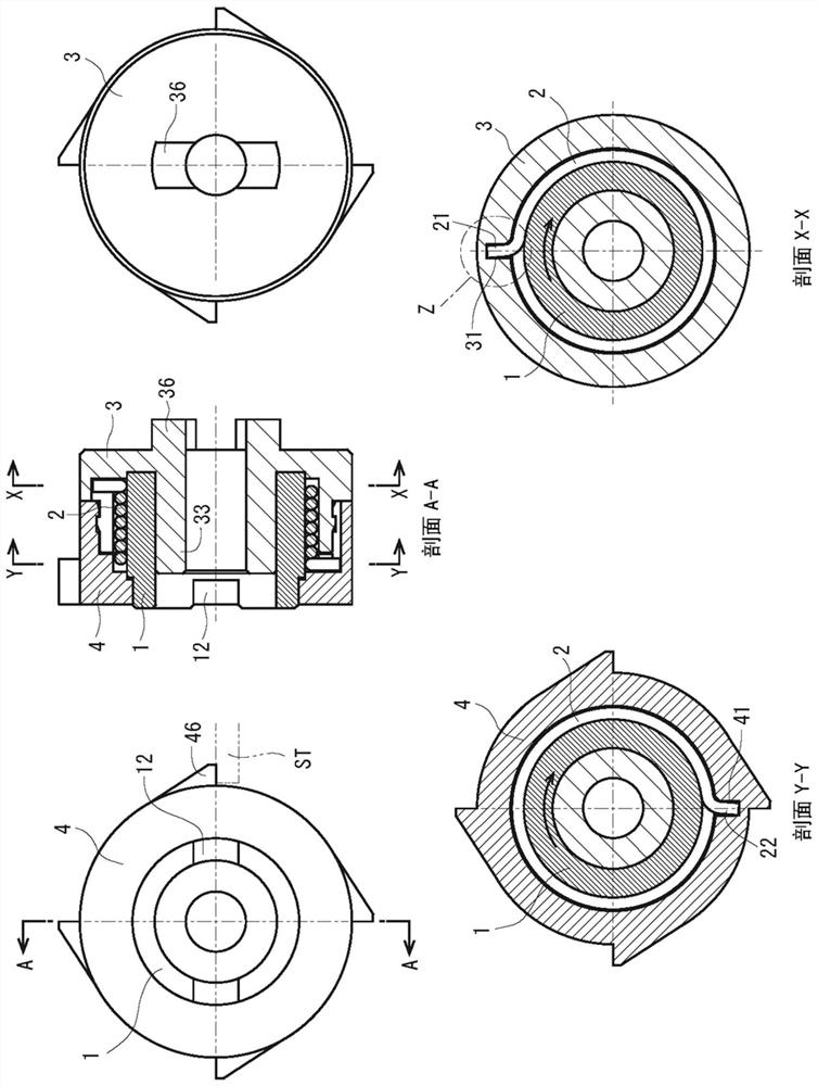
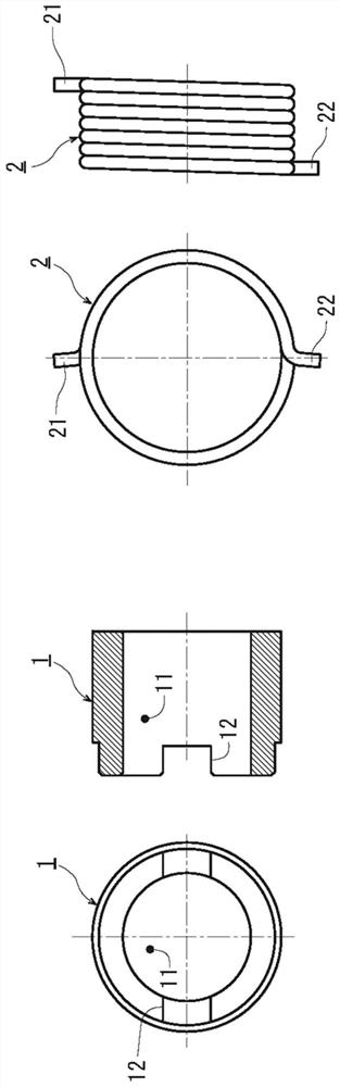
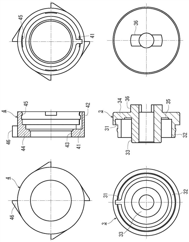
[0056] Hereinafter, the spring clutch of the present invention will be described based on the drawings. figure 1 The overall structure (assembly drawing) of the embodiment of the spring clutch of the present invention is shown, figure 2 The components of the spring clutch, namely the rotating body and the coil spring, are shown in a single-piece diagram. image 3 The output and control components are represented as single-piece diagrams. also, Figure 4 The state in which the rotary body to which the coil spring is attached and the output member are combined is shown, and the hook portion inserted into the slit is shown in an enlarged view.

[0057] like figure 1 As shown, the spring clutch of this embodiment is composed of four parts: a rotating body 1 , an output member 3 , a control member 4 , and a coil spring 2 wound around the outer circumference of the rotating body 1 . The rotating body 1 is formed in a cylindrical shape (see also figure 2 The single-piece dia...


PUM


Abstract

The present invention provides a spring clutch that rotationally transmits tightening torque of a coil spring attached to a rotating body to an output member, which can prevent a reduction in the durability of a hook portion due to a bending moment and can perform smooth rotational transmission. A coil spring (2) is installed on the outer periphery of the rotating body (1) of the spring clutch, and the opening of the slit (31) inserted into the hook (21) at one end of the coil spring (2) of the output member (3) Smaller chamfers are provided. When the rotating body (1) rotates and transmits the fastening torque of the coil spring (2) to the output member (3), the connecting portion between the curved portion and the straight portion of the hook portion (21) abuts against the chamfer Therefore, no bending stress due to bending moment will be generated in the hook portion (21) during rotation transmission, and the hook portion can be prevented from being damaged. In addition, the guide part (33) fits tightly into the hollow part of the rotating body (1), preventing the central axis from shifting and tilting.

Description

technical field [0001] The present invention relates to a spring clutch in which a coil spring is attached to the outer periphery of a rotating body, and when the coil spring is tightened by the rotation of the rotating body, the rotation is transmitted to the output side, and when the coil spring is loosened , which blocks the rotation transfer. Background technique [0002] The spring clutch is a clutch in which the frictional force acting between the rotating body and the coil spring wound around the outer circumference is different depending on the tightening or loosening of the coil spring, and the rotation transmission is blocked or turned on by utilizing this fact. . The clutch has a relatively simple structure, is reliable in operation, and is easily miniaturized, so it is widely used in office equipment such as copiers and printers. [0003] The inner diameter of the coil spring of the spring clutch is generally slightly smaller than the outer diameter of the rota...

Claims


Application Information

Patent Timeline
Patent Type & Authority Patents(China)
IPC IPC(8): F16D13/08F16D13/58F16F1/14F16F1/48
CPCF16D13/08F16D13/58F16F1/14F16F1/48
Inventor 井内晴日望月哲平野村聪
Owner ORIGIN CO LTD
Why Eureka
Try Eureka