Cross link interference measurement method and device and computer readable storage medium

An interference measurement, cross-link technology, applied in wireless communication, electrical components and other directions, can solve problems such as cross-link interference

Active Publication Date: 2019-02-26
CHINA MOBILE COMM LTD RES INST +1
View PDF15 Cites 15 Cited by
  • Summary
  • Abstract
  • Description
  • Claims
  • Application Information

AI Technical Summary

Problems solved by technology

However, when adjacent cells transmit information in different directions (uplink...

Method used


Image

  • Cross link interference measurement method and device and computer readable storage medium
  • Cross link interference measurement method and device and computer readable storage medium
  • Cross link interference measurement method and device and computer readable storage medium

Examples


Embodiment 1

[0141] In this embodiment, inter-user cross-link interference measurement is performed based on a sounding reference signal (Sounding reference signal, SRS). The specific process is as follows: Figure 9 As shown, specifically:

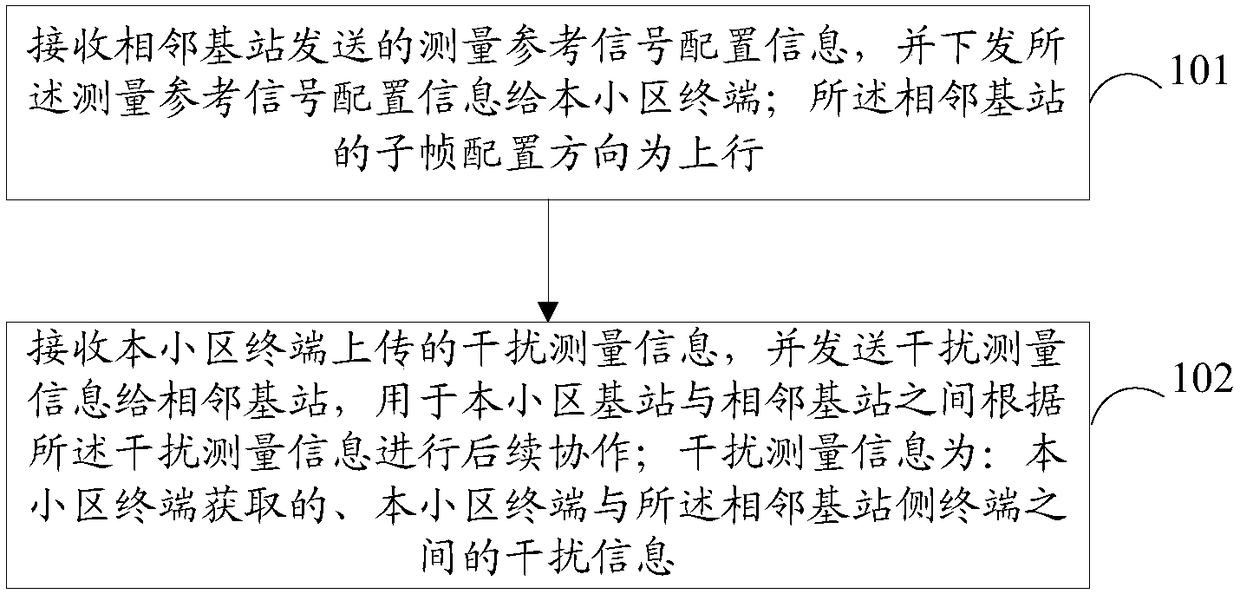
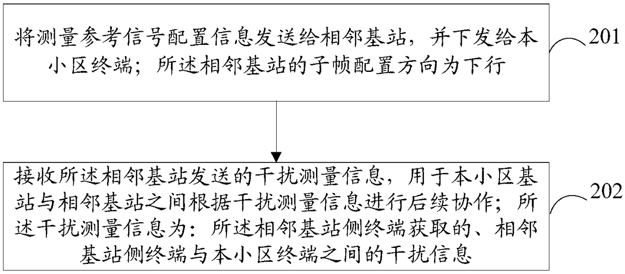
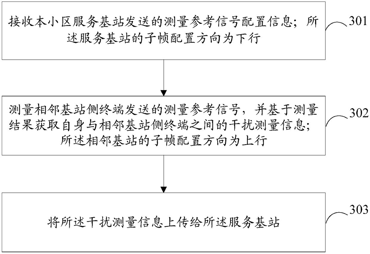
[0142] Step 901: base station 1 and base station 2 exchange the direction of subframe configuration through the backhaul link (X2 interface);

[0143] Here, the subframe of base station 1 will be configured in the downlink direction, and the subframe of base station 2 will be configured in the uplink direction. In this case, user UE2 served by base station 2 will generate a UE-UE interaction with cell UE1 served by base station 1. cross-link interference.

[0144] Step 902: Base station 2 exchanges the SRS configuration information to the neighboring base station base station 1 through the backhaul link (X2 interface), and at the same time, base station 2 indicates the SRS configuration information to UE2 in the cell;

[0145] Here, the SRS configur...

Embodiment 2

[0153] Such as Figure 10 As shown, the intermediate base station (serving j UEs) will be configured as uplink subframes, and other surrounding base stations will be configured as downlink subframes (the surrounding base stations may not all be configured as downlink subframes). At this time, the base station will configure the surrounding Users in base station 1 (serving m UEs), base station 2 (serving n UEs), and base station 3 (serving k UEs) bring cross-link interference between UEs, that is, the middle uplink base station sends SRS, and the surrounding downlink base stations The serving UE performs interference measurements.

[0154] exist Figure 10 In the scenario shown, the uplink base station and the surrounding base stations first exchange subframe direction information through backhaul / X2, and at the same time, the uplink base station exchanges the SRS configuration information configured for each UE in the cell to the surrounding base stations. The surrounding ba...

Embodiment 3

[0157] Such as Figure 11 As shown, the intermediate base station (serving j UEs) will be configured as a downlink subframe, and other surrounding base stations will be configured as an uplink subframe (the surrounding base stations may not all be configured as an uplink subframe). At this time, the surrounding base stations 1 ( Serving m UEs), base station 2 (serving n UEs) and base station 3 (serving k UEs) will bring cross-link interference between UEs to users served by the intermediate base station. That is, the surrounding uplink base stations send SRS, and the UE served by the intermediate downlink base station performs interference measurement.

[0158]The difference from the second embodiment is that the intermediate downlink base station needs to measure the SRS sent by the surrounding base station 1, base station 2, and base station 3 serving users. The intermediate base station and the surrounding base stations first exchange subframe configuration direction infor...


PUM


Abstract

The embodiment of the present invention provides a cross link interference measurement method and device and a computer readable storage medium. When the method is applied to a base station whose downlink configuration direction is a downlink direction, the method includes the steps: receiving measurement reference signal configuration information sent by a neighboring base station and transmitting the measurement reference signal configuration information to a local cell terminal, wherein the subframe configuration direction of the neighboring base station is an uplink direction; receiving interference measurement information uploaded by the local cell terminal, and transmitting the interference measurement information to the neighboring base station so as to perform subsequent cooperation between the base station and the neighboring base station according to the interference measurement information, wherein the interference measurement information is the interference information, which is obtained by the local cell terminal, between the local cell terminal and a terminal of the neighboring base station.

Description

technical field [0001] The present invention relates to the technical field of mobile communication, in particular to a cross-link interference measurement method, device and computer-readable storage medium. Background technique [0002] There are two duplex modes in traditional mobile communication systems, namely: Frequency Division Duplex (FDD) and Time Division Duplex (TDD). With the development of communication technology, it is difficult for traditional TDD and FDD systems to better match the diverse business requirements of 5G networks. In order to meet the duplex technology convergence of the future 5G new air interface, the industry has proposed a flexible duplex technology. [0003] Flexible duplex technology breaks through the fixed allocation of uplink and downlink resources in traditional cellular network systems, and adaptively adjusts uplink and downlink resources according to business needs, thereby improving spectrum utilization and indirectly eliminating ...

Claims


Application Information

Patent Timeline
IPC IPC(8): H04W24/02
CPCH04W24/02
Inventor 王爱玲倪吉庆左君徐国珍
Owner CHINA MOBILE COMM LTD RES INST
Why Eureka
Try Eureka