Robot clamp with functions of automatic object discharging and direction adjusting

A robot fixture and direction adjustment technology, applied in the direction of chucks, manipulators, manufacturing tools, etc., can solve the problems of reducing the contact area of ​​the workpiece, difficult to perform due, rotation and slippage, etc.

Inactive Publication Date: 2019-03-01
DONGGUAN UNIV OF TECH
View PDF1 Cites 4 Cited by
  • Summary
  • Abstract
  • Description
  • Claims
  • Application Information

AI Technical Summary

Problems solved by technology

[0002] With the rapid development of robot technology, industrial robots have been widely used in various fields. In logistics palletizing operations, using robots to grab workpieces for automatic palletizing can reduce labor intensity and improve palletizing efficiency. Today, industrial robots are widely used in my country's industrial The field of application is becoming more and more extensive. With the popularity of robots, the movements of robots and their grippers are not flexible enough and are subject to many restrictions. Especially in the application level of palletizing and handling industries, it is difficult to give full play to their due advantages
[0003] A robot gripper is disclosed in the Chinese invention patent application publication specification CN104772766 A. Although the pressing wheel of the robot gripper is covered with an elastic material, it can increase the clamping force when clamping the workpiece, and can also To effectively protect the appearance of the workpiece and avoid damage to the workpiece, the clamping surface at the end of the gripper fixture of the present invention is set as an arc surface, and the design of the clamping surface as an arc surface makes the clamping surface of the gripper of the fixture consistent with the circular pipe workpiece or the arc surface The workpiece is matched with the workpiece, and is suitable for stably clamping the workpiece of the above shape. When the clamping surface is set as an arc surface, the pressing wheel is arranged on the upper end surface and the lower end surface of the clamping surface, thereby improving the clamping surface of the arc surface. Clamping strength, but the contact area with the workpiece is reduced, and the pressure wheel will rotate and slip on the workpiece, causing the grasped workpiece to fall off

Method used


Image

  • Robot clamp with functions of automatic object discharging and direction adjusting
  • Robot clamp with functions of automatic object discharging and direction adjusting
  • Robot clamp with functions of automatic object discharging and direction adjusting

Examples


Embodiment Construction

[0030] The following will clearly and completely describe the technical solutions in the embodiments of the present invention with reference to the accompanying drawings in the embodiments of the present invention. Obviously, the described embodiments are only some, not all, embodiments of the present invention.

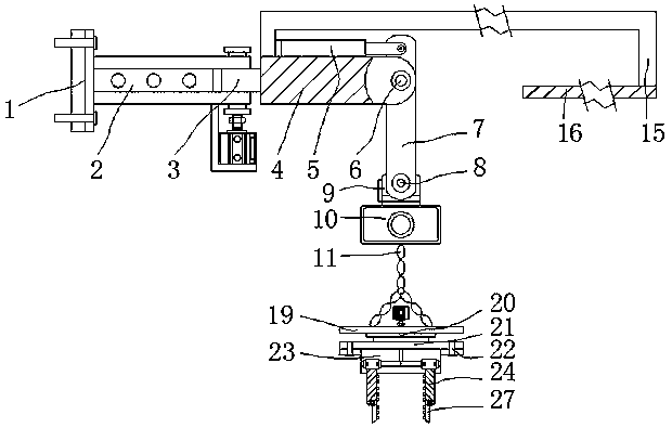
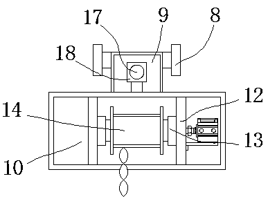
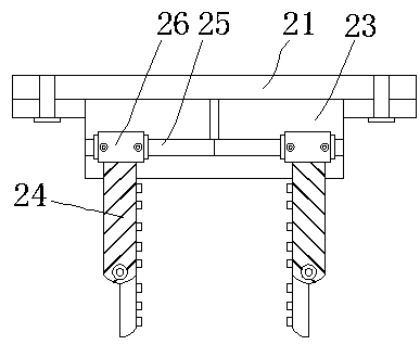
[0031] In the description of the present invention, unless otherwise stated, the meaning of "plurality" is two or more; the terms "upper", "lower", "left", "right", "inner", "outer" , "front end", "rear end", "head", "tail", etc. indicate the orientation or positional relationship based on the orientation or positional relationship shown in the drawings, and are only for the convenience of describing the present invention and simplifying the description, rather than Indicates or implies that the device or element referred to must have a particular orientation, be constructed and operate in a particular orientation, and therefore should not be construed as limiting the...


PUM


Abstract

The invention relates to a robot clamp with functions of automatic object discharging and direction adjusting, and relates to the technical field of robot clamps. The robot clamp comprises a connecting flange and a second mechanical arm. A first mechanical arm is arranged on the right side of the connecting flange. A first rotating shaft is arranged on the right side in the first mechanical arm. The second mechanical arm is inlaid on the right side of the first rotating shaft. The robot clamp has the advantages that a third mechanical arm rotates on the second mechanical arm along a second rotating shaft, the height of grabbed workpieces can be improved, the second mechanical arm can rotate on the first mechanical arm along the first rotating shaft, and the workpieces can be driven to rotate; and the workpieces are rotated to the direction of the position where the workpieces need to be placed, the workpieces do not need to be rotated or moved by a whole robot, the situation that the rotating amplitude of the robot is larger than that of the second mechanical arm, and consequently the workpieces move or fall off in the direction changing process is avoided, and therefore the workpieces are more stable after being grabbed.

Description

technical field [0001] The invention relates to the technical field of robot grippers, in particular to a robot gripper with automatic discharge adjustment direction. Background technique [0002] With the rapid development of robot technology, industrial robots have been widely used in various fields. In logistics palletizing operations, using robots to grab workpieces for automatic palletizing can reduce labor intensity and improve palletizing efficiency. Today, industrial robots are widely used in my country's industrial The application in the field is becoming more and more extensive. With the popularity of robots, the movements of robots and their grippers are not flexible enough and subject to many restrictions. Especially in the application level of the palletizing and handling industry, it is difficult to give full play to their due advantages. [0003] A robot gripper is disclosed in the Chinese invention patent application publication specification CN104772766 A. Al...

Claims


Application Information

Patent Timeline
Patent Type & Authority Applications(China)
IPC IPC(8): B25J9/12B25J15/02B25J15/10B25J15/00B25J19/00
CPCB25J9/12B25J15/0028B25J15/0293B25J15/10B25J19/00
Inventor 孙小傅马宏伟孙振忠
Owner DONGGUAN UNIV OF TECH
Why Eureka
Try Eureka