priority diverter valve

A diverter valve, spool technology, used in multi-port valves, valve devices, fluid steering mechanisms, etc.

Inactive Publication Date: 2002-11-13
SHIMADZU SEISAKUSHO CO LTD
View PDF2 Cites 0 Cited by
  • Summary
  • Abstract
  • Description
  • Claims
  • Application Information

AI Technical Summary

Problems solved by technology

[0009] In order to solve the above-mentioned contradictory problems, the present invention effectively exerts the damping effect when the spool is at the steering operation position, and r

Method used


Image

  • priority diverter valve
  • priority diverter valve
  • priority diverter valve

Examples


Embodiment Construction

[0022] An embodiment of the present invention will be described below with reference to the drawings.

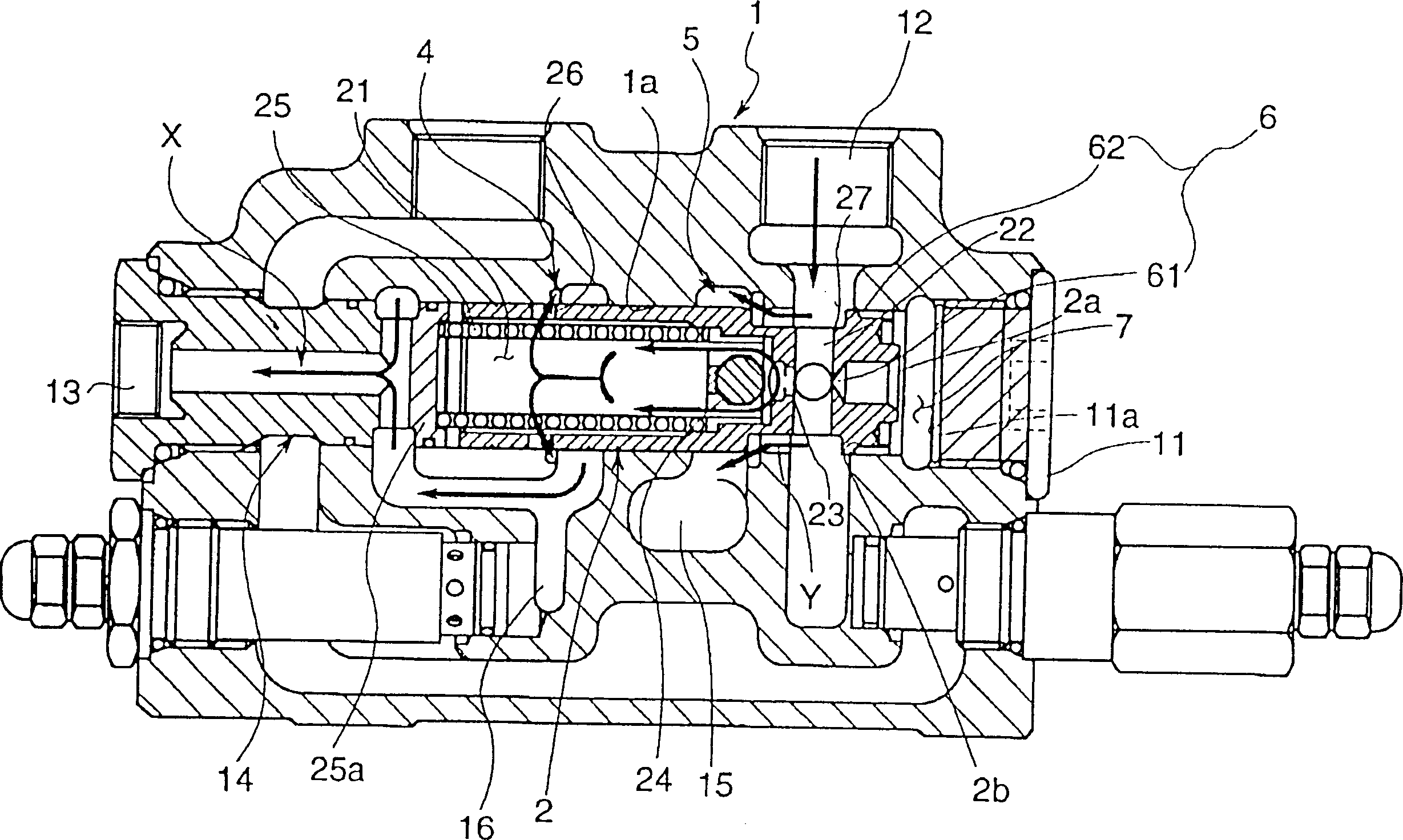
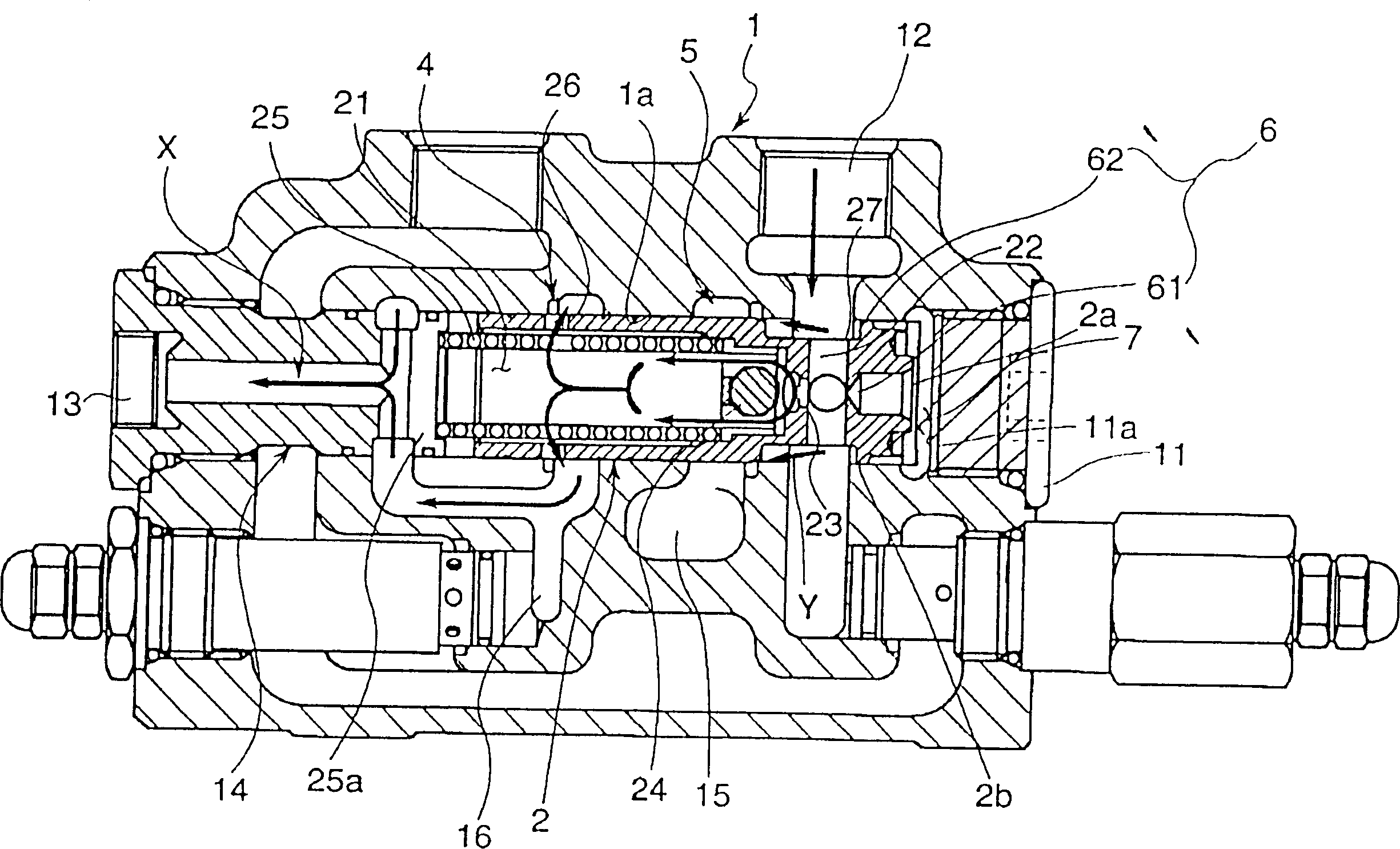
[0023] The priority diverter valve of this embodiment, for example, is used for forklifts, and the pressurized liquid such as oil provided from the common hydraulic source is preferentially diverted to the steering control, and the remaining part is diverted to the loading and unloading control according to the requirements, such as figure 1 As shown, the main body 1 is equipped with a spool 2 and a spring 25 to form.

[0024] There is a spool guide hole 1a in the body 1, the spool 2 is inserted in the spool guide hole 1a, and one end of the guide hole is blocked with a plug 11. In the main body, a high-pressure port 12 is provided at one end of the spool guide hole 1a, and a steering port 13 is provided at the other end of the port through a priority control joint 14 . In addition, at the position close to the interface 12 in the main body, while the loading and unloading ...


PUM


Abstract

A priority type diverter valve is to make the aperture of the small hole (61) of the damping hole (6) unchanged, cut a cutout (62) on the valve column (2), pass through the cutout (62), and divide into two stages A device that switches the damping effect. For this reason, during steering operation, the joint (62) is not opened to improve the damping effect, while the spool (2) acts on the spool (2) to act on the sufficient holding force required to suppress the oscillation, the joint (62) is opened when moving to reduce the damping effect, The drag resistance of the spool (2) is reduced, and a quick response characteristic can be obtained. The valve can take into account the stability of the steering operation and the fast switching characteristics between the operating states.

Description

technical field [0001] The present invention relates to a priority type diverter valve suitable for steering and loading and unloading control by using pressurized liquid from a common hydraulic source like forklifts. Background technique [0002] For example, forklifts, etc., use the diverter valve to divert the pressurized liquid provided by a single hydraulic source, giving priority to ensuring a certain flow is used for steering, and the remaining flow is supplied to loading and unloading operations. In this way, a diverter valve that preferentially secures a certain flow rate for a specific purpose such as steering is called a priority diverter valve. [0003] However, the existing priority diverter valve has a body with a high-pressure port, a port for steering, and a port for loading and unloading; it can slide in the body, and guide the pressurized liquid in the high-pressure port to the port for steering through the control hole, and directly Guide to the spool of ...

Claims


Application Information

Patent Timeline
IPC IPC(8): F15B13/06B62D5/07F15B13/02F15B13/04
CPCB62D5/07F15B13/022F15B13/0407Y10T137/2524Y10T137/2688
Inventor 山下茂
Owner SHIMADZU SEISAKUSHO CO LTD
Why Eureka
Try Eureka