Supercharge Your Innovation With Domain-Expert AI Agents!

Flapping wing fan surface, ornithopter wing and ornithopter

A technology of orthopter and fan, which is applied in the field of aircraft, can solve the problems of small thrust and limit the flight performance of orthopter, and achieve the effect of increasing thrust, increasing flight performance and increasing flexibility

Inactive Publication Date: 2019-03-05
周袭明
View PDF6 Cites 0 Cited by
  • Summary
  • Abstract
  • Description
  • Claims
  • Application Information

AI Technical Summary

Problems solved by technology

[0003] But the wing that the existing orthopter adopts is fixed wing, and the thrust that it produces is less, has limited the flight performance of ortho-wing

Method used


Image

  • Flapping wing fan surface, ornithopter wing and ornithopter
  • Flapping wing fan surface, ornithopter wing and ornithopter
  • Flapping wing fan surface, ornithopter wing and ornithopter

Examples


Embodiment 1

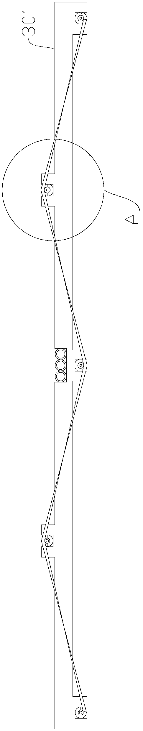
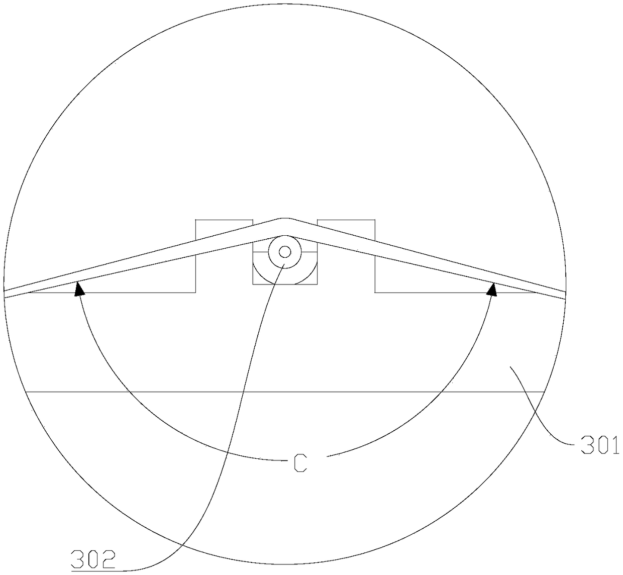
[0038] see Figure 1 to Figure 5 As shown, Embodiment 1 of the present invention provides a flapping wing fan, including end trusses 301, support rods 302 and skins 303, the number of support rods 302 is multiple, and multiple support rods 302 are fixed to the end trusses 301 , and a plurality of support rods 302 are used to support and fix the skin 303; a plurality of support rods 302 are distributed in parallel and spaced along the length direction of the end truss 301, and in the height direction of the end truss 301, two adjacent support rods 302 is arranged in a dislocation up and down.

[0039] Specifically, along the length direction of the end truss 301, a plurality of support rods 302 are arranged at equal intervals, that is to say, the distance between two adjacent support rods 302 is equal; the axis directions of the plurality of support rods 302 are parallel . The length direction of the end truss 301 is parallel to the span direction of the wing body 401 of the ...

Embodiment 2

[0057] Embodiment 2 of the present invention provides a flapping wing, including the flapping wing fan provided in Embodiment 1.

[0058] see Image 6 As shown, in this embodiment, the flapping wing aircraft wing also includes a wing body 401, and the number of flapping wing sectors is multiple, and a plurality of flapping wing sectors are distributed at equal intervals along the span direction of the wing body 401, and a plurality of flapping wing sectors The fan is close to the tip of the wing body 401 and away from the root of the wing body 401 . The flapping fan is fixedly connected to the trailing edge of the wing. During the swinging process of the entire wing body structure, the flapping wing fan can swing with the wing body to provide thrust and lift. The resistance of the flapping wing is small, which is beneficial to the take-off and flight of the flapping wing.

Embodiment 3

[0060] Embodiment 3 of the present invention provides an orthoplane, including the orthoplane wing provided in Embodiment 2. It should be noted that the orthopter can be an unmanned or a manned oropter.


PUM


Abstract

The invention relates to the technical field of aircrafts, concretely to a flapping wing fan surface, an ornithopter wing and an ornithopter. The flapping wing fan surface includes an end truss, supporting rods and a skin. The number of the supporting rods is multiple. The multiple supporting rods are fixed to the end truss. The multiple supporting rods are used for supporting and fixing the skin.The multiple supporting rods are distributed in parallel along the length direction of the end truss, and the two adjacent supporting rods are up-down misaligned in the height direction of the end truss. The ornithopter wing includes the flapping wing fan surface. The ornithopter includes the ornithopter wing. According to the invention, the thrust of the ornithopter is increased, which is beneficial of the increasement of the flight performance of the ornithopter.

Description

technical field [0001] The invention relates to the technical field of aircraft, in particular to a flapping-wing fan, a wing of a flapping-wing airplane and a flapping-wing airplane. Background technique [0002] The orthopter, also known as the thopter, refers to a heavier-than-air aircraft whose wings can flutter up and down like the wings of birds and insects. The flapping wings not only generate lift, but also generate forward propulsion. Modern flapping-wing aircraft are divided into bird-like flapping wings and insect-like flapping wings in principle, with micro-sized unmanned flapping wings as the main ones. Bird-like flapping wings have low flapping frequency and large wing area, similar to bird flight, and are relatively easy to manufacture; insect-like flapping wings have high flapping frequency, small wing area, and high manufacturing difficulty, but they can easily achieve hovering. The bionic orthopter has great advantages in military and civilian use, and has...

Claims


Application Information

Patent Timeline
Patent Type & Authority Applications(China)
IPC IPC(8): B64C33/02
CPCB64C33/02
Inventor 周袭明
Owner 周袭明
Features
  • R&D
  • Intellectual Property
  • Life Sciences
  • Materials
  • Tech Scout
  • Unparalleled Data Quality
  • Higher Quality Content
  • 60% Fewer Hallucinations
Learn More