
Internal waverider-derived hypersonic inlet with ordered inlet and outlet shape and design method

A hypersonic, air inlet technology that is used in turbine/propulsion inlets, combustion air/combustion-air handling, engine components, etc. to widen the operating Mach number range

Inactive Publication Date: 2009-04-29
NANJING UNIV OF AERONAUTICS & ASTRONAUTICS
View PDF0 Cites 25 Cited by
  • Summary
  • Abstract
  • Description
  • Claims
  • Application Information

AI Technical Summary

Problems solved by technology

However, due to the inherent characteristics of the three-dimensional shrinkage inlet, the existing various design technologies cannot meet the requirements of regular and customizable inlet and outlet shapes on the premise of ensuring the aerodynamic performance of the inlet.

Method used


Image

  • Internal waverider-derived hypersonic inlet with ordered inlet and outlet shape and design method
  • Internal waverider-derived hypersonic inlet with ordered inlet and outlet shape and design method
  • Internal waverider-derived hypersonic inlet with ordered inlet and outlet shape and design method

Examples


Embodiment 1

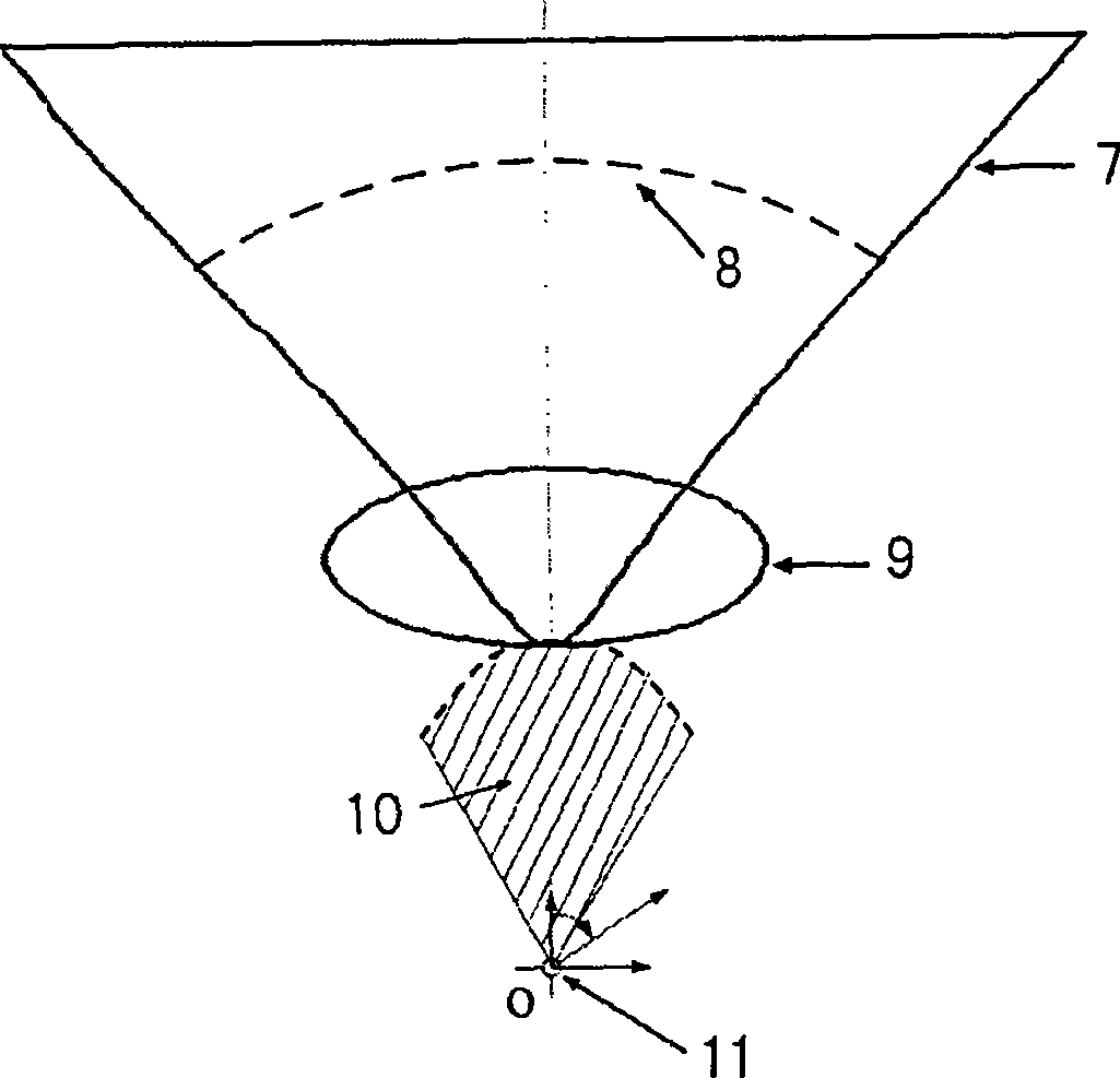
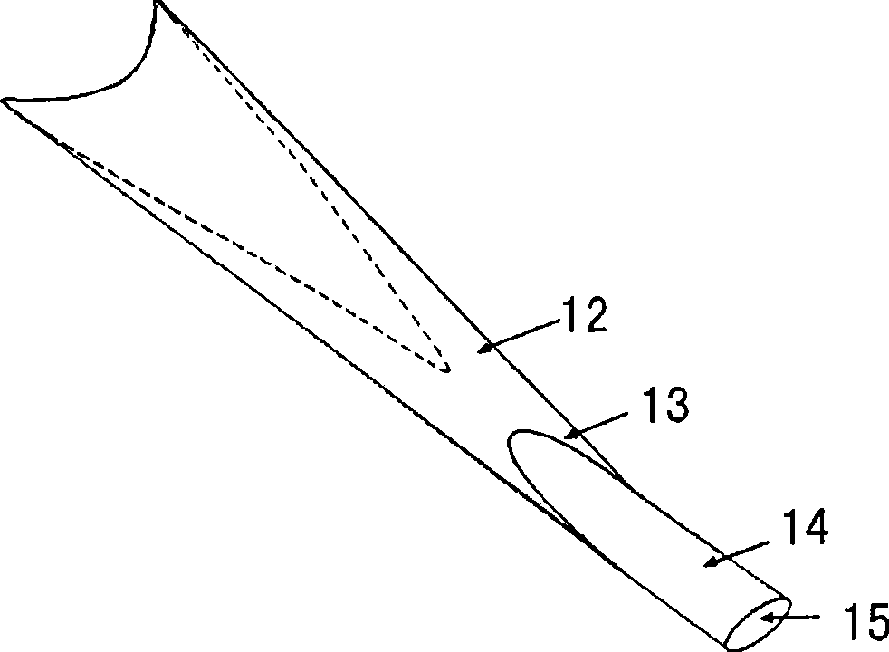
[0029] At the flow Mach number 5, the design such as figure 1A series of axisymmetric internal contraction basic flow fields are shown, the generatrix of the internal contraction turning wall is a cubic curve, and the initial internal contraction angle is 8 degrees. The design requirements for the shape of the inlet are: the outlet of the inlet is an ellipse with a specified long-short axis ratio of 2.5, and the projected shape of the inlet is a triangle (such as figure 2 ). Figure 3 is a three-dimensional profile of an inner waveriding hypersonic inlet (triangular inlet, elliptical outlet) whose inlet and outlet shapes can be customized. Under the design state of incoming flow Mach number 5, the calculation performance of the inlet is 13.2 for the average outlet pressure ratio, 2.72 for the outlet Mach number, 0.62 for the total pressure recovery, and 0.99 for the flow capture coefficient.

Embodiment 2

[0031] At the flow Mach number 5, the design such as figure 1 A series of axisymmetric internal contraction basic flow fields are shown, the generatrix of the internal contraction turning wall is a cubic curve, and the initial internal contraction angle is 8 degrees. The design requirements for the shape of the inlet are: the outlet of the inlet is an ellipse with a specified long-to-short axis ratio of 2.5, and the projected shape of the inlet is approximately square (such as Figure 4 ). The shape of the inlet and outlet can be customized. The three-dimensional contour of the inner waveriding hypersonic inlet (approximately square inlet, oval outlet) (as shown in Figure 5). Under the design state of incoming flow Mach number 5, the calculated performance of the inlet is 14.0 for the average outlet pressure ratio, 2.75 for the outlet Mach number, 0.62 for the total pressure recovery, and 0.99 for the flow capture coefficient. In the wind tunnel experiment of Mach 5, the ove...


PUM


Abstract

The invention discloses an internal waverider-derived high supersonic inlet duct, the shapes of the inlet and outlet of which can be customized, and a design method thereof. The structure of the internal waverider-derived high supersonic inlet duct comprises an inlet duct contraction section and an isolated section, wherein the shape of the inlet duct contraction section is in three dimensional inward contraction. The design method is that a non-axisymmetric internal contraction basic flow field is taken as the base, the non-axisymmetric internal contraction basic flow field comprises an axisymmetric internal contraction rotary wall surface and a non-axisymmetric variable radius central body, wherein the axisymmetric internal contraction rotary wall surface keeps no changing, and the radius of the central body is adjustable. The invention has the advantages that the internal waverider-derived high supersonic inlet duct can capture the inflow by full flow and has low Mach number automatic overflow; the shapes of the inlet and the outlet can be customized according to the layout requirement, and the parallel module installation or the integrated design with various aircrafts can be easily realized.

Description

technical field [0001] The invention relates to an internal wave-riding hypersonic air inlet with customizable inlet and outlet shapes and a design method thereof, belonging to the technical field of hypersonic air inlets. Background technique [0002] Hypersonic flight refers to the flight whose Mach number is greater than 5. Its development involves national security and peaceful use of space, and it is one of the focuses of the current international competition for space technology. The inlet duct is a major component in a hypersonic vehicle, and its design goal is to provide as much high-energy airflow as possible to the downstream propulsion system components with minimal flow loss. From a technical point of view, the design requirements of the hypersonic inlet mainly include the following points: ①The design state has a strong flow capture capability, and provides as much flow as possible for the propulsion system; ②When compressing the airflow to the required pressure...

Claims


Application Information

Patent Timeline
Patent Type & Authority Applications(China)
IPC IPC(8): F02C7/04
Inventor 尤延铖黄国平郭军亮朱呈祥梁德旺
Owner NANJING UNIV OF AERONAUTICS & ASTRONAUTICS
Learn More