Internal combustion engine airflow management systems and methods

A technology of air flow and management system, applied in air cooling, electrical control, mechanical equipment, etc., can solve the problem of unpredictable future health status and service life of sensors

Active Publication Date: 2019-03-05
GM GLOBAL TECH OPERATIONS LLC
View PDF7 Cites 2 Cited by
  • Summary
  • Abstract
  • Description
  • Claims
  • Application Information

AI Technical Summary

Problems solved by technology

Therefore, such controllers may not be able to predict the future health and / or remaining useful life of the sensor

Method used


Image

  • Internal combustion engine airflow management systems and methods
  • Internal combustion engine airflow management systems and methods
  • Internal combustion engine airflow management systems and methods

Examples


Embodiment Construction

[0017] Embodiments of the disclosure are described herein. It should be understood, however, that the disclosed embodiments are merely examples and that other embodiments may assume various and alternative forms. The figures are not necessarily to scale; some features may be exaggerated or minimized to show details of particular components. Therefore, specific structural and functional details disclosed herein are not to be interpreted as limiting, but merely as a representative basis for teaching one skilled in the art to variously employ the present invention. As will be understood by those of ordinary skill in the art, various features illustrated and described with reference to any one figure may be combined with features illustrated in one or more other figures to create embodiments not explicitly illustrated or described. The illustrated combinations of features provide representative embodiments for typical applications. However, particular applications or implementat...


PUM


Abstract

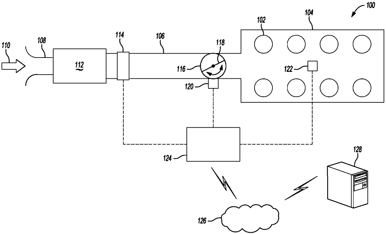
An airflow management system for an internal combustion engine comprises: an inlet portion to receive ambient air and a mass airflow (MAF) sensor adapted to sense mass flow rate of air passed throughthe inlet portion. The airflow management system comprises a throttle body to selectively restrict airflow and a throttle position sensor (TPS) adapted to sense an opening value of the throttle body.The airflow management system comprises an intake manifold in fluid connection with the throttle body and configured to direct airflow to each of a plurality of combustion cylinders. A manifold air pressure (MAP) sensor is adapted to sense air pressure at the intake manifold. A controller is programmed to monitor signals from each of the MAF sensor, TPS, and the MAP sensor, and generate a residualerror value based on a difference between a model-based value and a corresponding monitored signal. A response action is based on the trend of at least two residual error values.

Description

technical field [0001] The present disclosure relates to prognostics and diagnostics for air flow management systems. Background technique [0002] Certain controllers monitor sensor data associated with corresponding vehicle systems and can diagnose faults present in these sensors. This technique is reactive in nature and can be limited to current state conditions without estimating fault severity or predicting any degradation in sensors. Therefore, such controllers may not be able to predict the future state of health and / or remaining useful life of the sensor. Contents of the invention [0003] An air flow management system for an internal combustion engine includes an inlet section for receiving ambient air and a mass air flow (MAF) sensor adapted to sense a mass flow of air passing through the inlet section. The air flow management system also includes a throttle body including a valve for selectively restricting air flow from the inlet portion and a throttle positi...

Claims


Application Information

Patent Timeline
Patent Type & Authority Applications(China)
IPC IPC(8): F02D41/00F02D41/22
CPCF02D41/0002F02D41/221F02D41/222F02D41/18F02D11/106F02D11/107F02D41/2464F02D2200/0402F02D2200/0406F02D9/02G07C5/0808G07C5/0816G07C5/0841F01P1/02F02D2009/0244F02D2009/022F02D2009/0235
Inventor C·桑卡瓦拉姆段时鸣L·威金斯S·利瓦伊约基D·索雷尔T·库兹马诺维
Owner GM GLOBAL TECH OPERATIONS LLC
Why Eureka
Try Eureka