A device for connecting and fixing a router with a network cable connector

A technology for fixing devices and network cable joints, which is applied to the parts, connections, coupling devices, etc. of the connecting device, which can solve problems such as different sizes, affecting the effect of router ventilation and heat dissipation, poor network contact, etc., and achieve the effect of improving the service life

Active Publication Date: 2021-12-03
深圳山泽基业科技有限公司
View PDF6 Cites 0 Cited by
  • Summary
  • Abstract
  • Description
  • Claims
  • Application Information

AI Technical Summary

Problems solved by technology

[0002] At present, the network has spread to every household, but when using the network, a router must be used. In some families or enterprises, several computers are connected to the router through a network cable. In the prior art, when the network cable is connected to the router , it is through the shrapnel in the network cable connector that is stuck in the router connection port that the network cable connector can be effectively fixed in the router connection port, and the network cable connector can be pulled out from the router connection port by pressing the shrapnel, because the network cable connector and the router connection port are more or less There will be some gaps, and the size will be different depending on the manufacturer, so when people touch the router or the network cable, there will be poor network contact, especially the network cable connector with damaged shrapnel, which is more likely to cause network contact. Bad situation, so people need to connect the network cable connector to the router port again to restore the use
[0003] In addition, most of the heat dissipation holes of the existing routers are on the bottom surface of the router. When people use the router, they directly place the router on the desktop or the ground. The effect of ventilation and heat dissipation will affect the service life of the router

Method used


Image

  • A device for connecting and fixing a router with a network cable connector
  • A device for connecting and fixing a router with a network cable connector
  • A device for connecting and fixing a router with a network cable connector

Examples


Embodiment Construction

[0017] The preferred embodiments of the present invention will be described in detail below in conjunction with the accompanying drawings: It should be understood that the preferred embodiments are only for illustrating the present invention, rather than limiting the protection scope of the present invention.

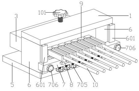
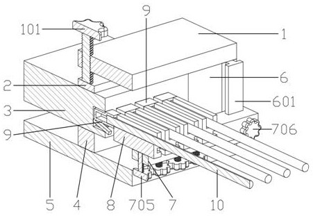
[0018] Such as Figures 1 to 4 As shown, a router and a network cable connector connection and fixing device, including a base 5, a second support plate 6 is respectively installed on both sides of the base 5, a router support plate 4 is also installed on the base 5, and the The router supporting board 4 is installed between the two second supporting boards 6 , and the first supporting board 1 is mounted on the upper ends of the two second supporting boards 6 . The first support plate 1 is provided with a third elastic screw 101, the central axis of the third elastic screw 101 is on the same straight line as the center of the router support plate 4, and the lower end of...


PUM


Abstract

The invention relates to a connection and fixing device for a router and a network cable joint, belonging to the technical field of communication equipment. It includes a base, a second support plate is installed on both sides of the base, a router support plate is also installed on the base, a first support plate is installed on the upper ends of the two second support plates, and the The first support plate is provided with a third elastic screw, the lower end of the third elastic screw is equipped with a router pressure plate, and one side of the two second support plates is jointly equipped with a support rod, and several support rods are installed in the support rod. A fixed mesh slider. The present invention fixes the router through the function of the router support plate and the router pressure plate, so that the bottom surface of the router is not in contact with the bottom plate, so as to solve the problem of poor heat dissipation caused by the ventilation fan on the bottom surface of the router, and effectively improve the service life of the router; The role of the block solves the problem of poor network contact when people touch routers or network cables.

Description

technical field [0001] The invention relates to a connection and fixing device for a router and a network cable joint, belonging to the technical field of communication equipment. Background technique [0002] At present, the network has spread to every household, but when using the network, a router must be used. In some families or enterprises, several computers are connected to the router through a network cable. In the prior art, when the network cable is connected to the router , it is through the shrapnel in the network cable connector that is stuck in the router connection port that the network cable connector can be effectively fixed in the router connection port, and the network cable connector can be pulled out from the router connection port by pressing the shrapnel, because the network cable connector and the router connection port are more or less There will be some gaps, and the size will be different depending on the manufacturer, so when people touch the rout...

Claims


Application Information

Patent Timeline
Patent Type & Authority Patents(China)
IPC IPC(8): H04Q1/02H04Q1/04H01R13/639
CPCH01R13/639H04Q1/028H04Q1/035H04Q1/04
Inventor 劳加斌符绩承
Owner 深圳山泽基业科技有限公司
Why Eureka
Try Eureka