
Conveyor for cold rolls after processing

A technology of conveying device and cold roll, which is used in transportation and packaging, trolley accessories, multi-axis trolley, etc., can solve the problems such as the inability to shock absorption, the inability to place cold rolls of different lengths through adjustment, and the inconvenience of placement and transfer.

Active Publication Date: 2020-04-10
江苏德祐精密钢管有限公司
View PDF2 Cites 0 Cited by
  • Summary
  • Abstract
  • Description
  • Claims
  • Application Information

AI Technical Summary

Problems solved by technology

[0006] In order to solve the above-mentioned technical problems, the present invention provides a conveying device for cold rolls after processing, to solve the first patent application number CN201420641647.8, the arc set on the fixed plate is fixed, when some cold rolls with smaller diameters are placed , the cold roll is easy to shake from side to side on the fixed plate, and the fixing effect is poor; secondly, the patent application number is CN201721754687.3, and the structure is not perfect, which is mainly reflected in that although the cold roll can be placed on the cart by using the spring However, when the cold roll is transported to a fixed position and transferred or placed, it cannot be damped; in addition, the existing equipment still has the following shortcomings: first, the structure is relatively fixed, and it can be The tonality is poor, for example, it is not possible to place cold rolls of different lengths through adjustment; shock absorption cannot be performed during transfer, and second, the transfer is not convenient enough. The problem of inconvenient placement and transfer after being transported to a fixed location

Method used


Image

  • Conveyor for cold rolls after processing
  • Conveyor for cold rolls after processing
  • Conveyor for cold rolls after processing

Examples


Embodiment

[0037] as attached figure 1 To attach Figure 9 Shown:

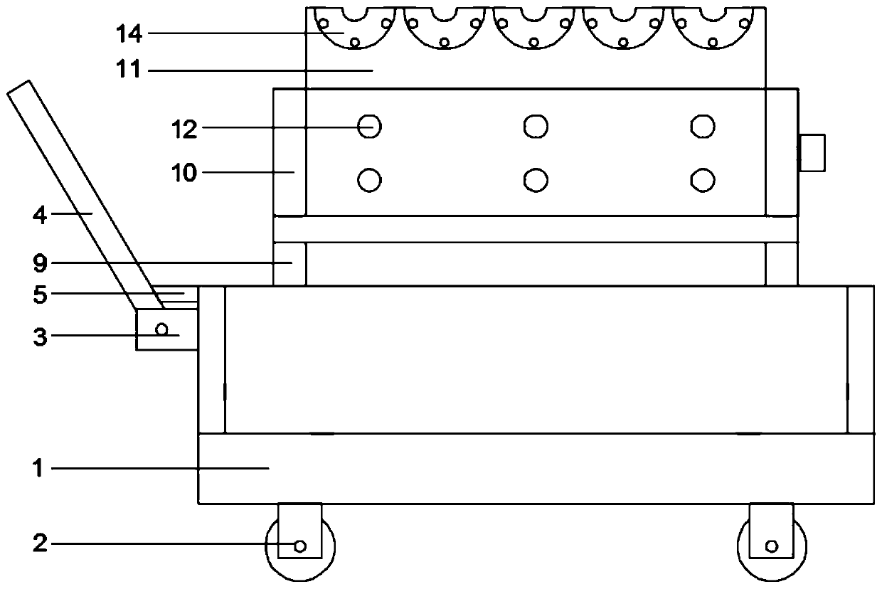
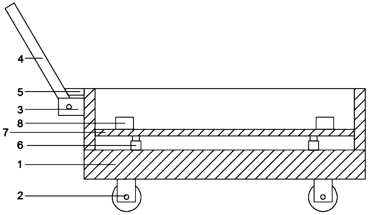
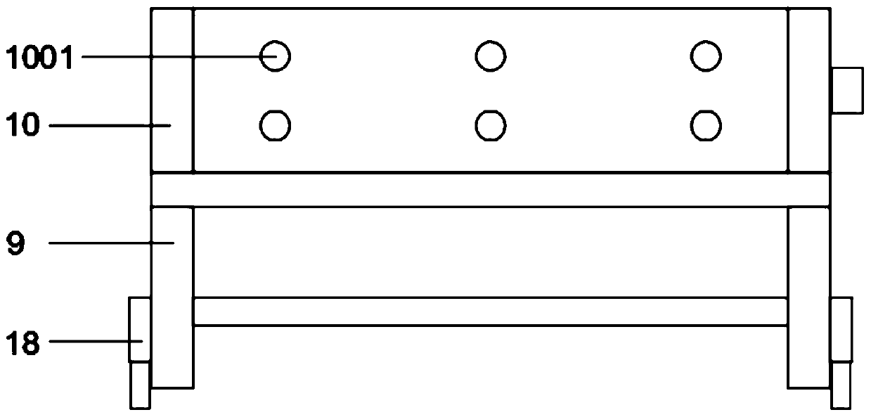
[0038] The present invention provides a conveying device for cold roll processing, including: cart body 1, universal wheel 2, rotating fixed frame 3, cart handle 4, trapezoidal iron 5, elastic telescopic rod A6, rectangular plate A7, Limiting angle iron 8, rectangular support frame 9, rectangular frame 10, circular hole A1001, rectangular plate B11, circular hole B1101, semicircular groove A1102, fixed shaft 12, semicircular plate A13, semicircular groove B1301, semicircular Plate B14, semicircular groove C1401, fixed pin 15, fixed bolt 16, jack structure 17 and elastic telescopic rod B18; four universal wheels 2 are welded on the bottom surface of the cart main body 1 in a rectangular array, and the cart main body 1 There is a rotating fixed frame 3 welded at the position above the left end face; the rotating fixed frame 3 is connected with a cart handle 4 through the rotation of the latch; the inner top surface of th...


PUM


Abstract

The invention provides a conveying device used after processing by cold rollers. The conveying device comprises a cart main body, a jack structure and elastic retractable rods B; four universal wheelsare welded to the bottom end face of the cart main body in a rectangular array shape; the left end face and right end face of the jack structure are welded and connected to the inner sides of two rectangular plates B respectively. Because of the arrangement of a rectangular support frame and the elastic retractable rods B, on the one hand, the elastic retractable rods B can play a damping role when the cold rollers are placed on the device; on the other hand, through arrangement of the rectangular support frame, convenience is provided when a forklift is used for transferring the cold rollers; thirdly, through the arrangement of the elastic retractable rods B, a damping effect can be achieved when the rectangular support frame on which the cold rollers are placed is placed on the ground.According to the conveying device, through the cooperative arrangement of the rectangular plates B, fixing shafts and the jack structure, the distance between the rectangular plates B can be adjusted,and therefore the conveying device is applicable to placement of the cold rollers different in length.

Description

technical field [0001] The invention belongs to the technical fields of transportation tools and steel processing, and more specifically relates to a conveying device for cold rolling after processing. Background technique [0002] The roll is an important part of the rolling mill in the rolling mill. It uses the pressure generated by a pair or a group of rolls to roll and roll the steel. It is mainly subjected to dynamic and static loads, wear and temperature changes during rolling. Due to the high value and high precision of the roll, the overall shape of the cold roll is cylindrical. When the general trolley is carrying such products, it is easy to slip out, which may cause damage to the product or injure the operator. It is necessary to propose a more suitable cold roll. and other means of transport for such products. [0003] For example, the application number: CN201420641647.8 is an expandable and shrinkable cold roll transport trolley, which includes a frame, suppo...

Claims


Application Information

Patent Timeline
Patent Type & Authority Patents(China)
IPC IPC(8): B62B3/04B62B3/02B62B5/00
CPCB62B3/02B62B3/04B62B5/00
Inventor 杨喜成
Owner 江苏德祐精密钢管有限公司
Learn More