A depth camera and depth camera protection method

A depth camera and light source technology, applied in the field of optics, can solve problems such as the inability to accurately detect the integrity of diffractive optical elements, and achieve the effects of avoiding laser safety problems, good protection, and accurate judgment results

Active Publication Date: 2022-03-29
SHENZHEN ORBBEC CO LTD
View PDF10 Cites 0 Cited by
  • Summary
  • Abstract
  • Description
  • Claims
  • Application Information

AI Technical Summary

Problems solved by technology

[0004] The purpose of the present invention is to provide a depth camera to solve the technical problem that the integrity of diffractive optical elements cannot be accurately detected in the prior art

Method used


Image

  • A depth camera and depth camera protection method
  • A depth camera and depth camera protection method
  • A depth camera and depth camera protection method

Examples


Embodiment Construction

[0055] In order to make the technical problems, technical solutions and beneficial effects to be solved by the present invention clearer, the present invention will be further described in detail below with reference to the accompanying drawings and embodiments. It should be understood that the specific embodiments described herein are only used to explain the present invention, but not to limit the present invention.

[0056]It should be noted that when a component is referred to as being "fixed to" or "disposed on" another component, it can be directly or indirectly located on the other component. When an element is referred to as being "connected to" another element, it can be directly or indirectly connected to the other element. Terms "top", "bottom", "left", "right", "front", "back", "vertical", "horizontal", "top", "bottom", "inside", "outer", etc. The indicated orientation or position is based on the orientation or position shown in the drawings, which is only for the...


PUM


Abstract

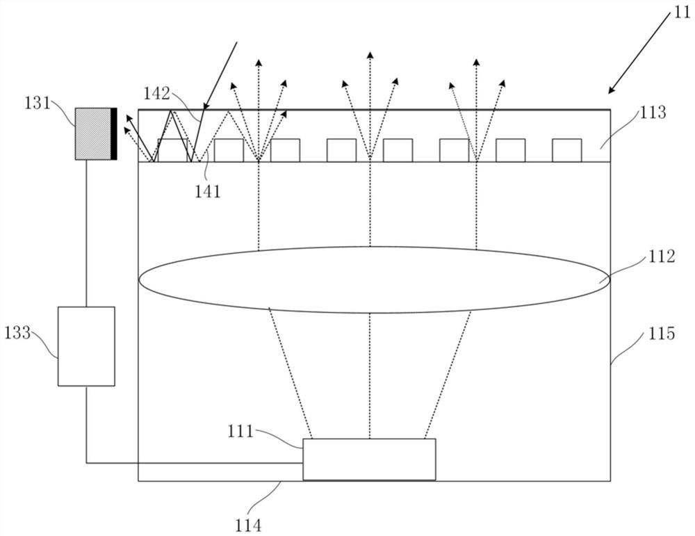
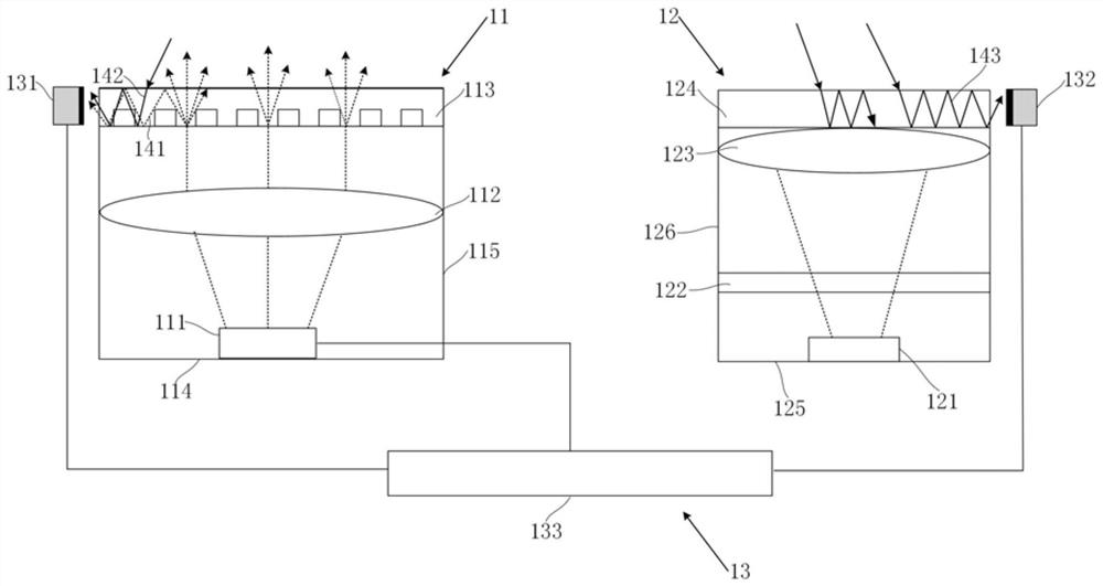
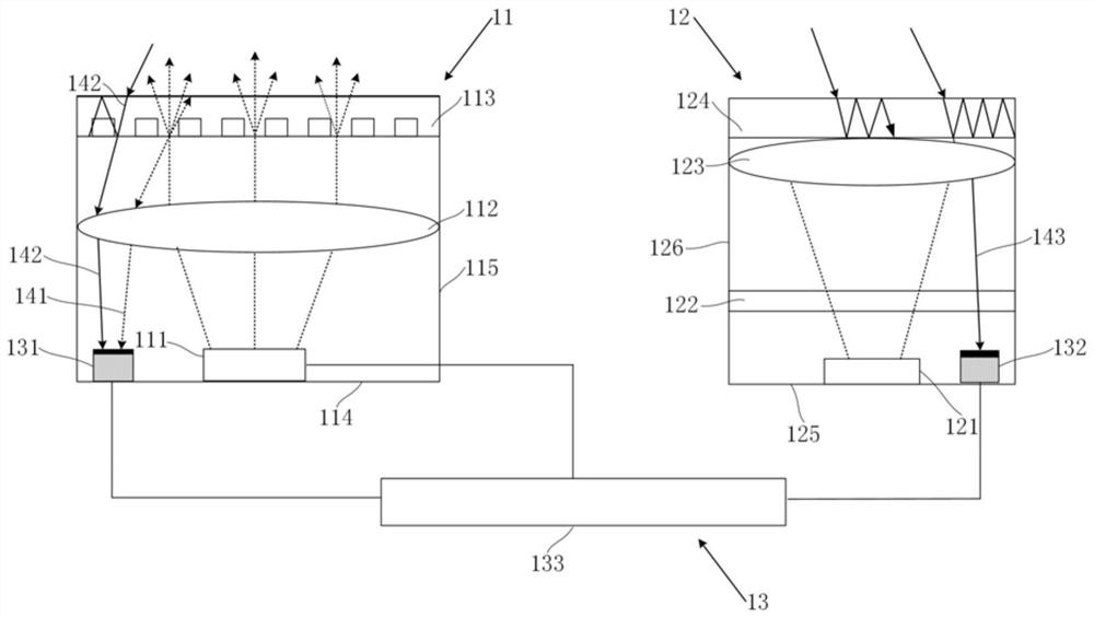
The present invention relates to the field of optical technology, and provides a depth camera and a protection method for the depth camera. The depth camera includes a projection module, an imaging module, and a monitoring module. The projection module includes a light source and a diffractive optical element. The imaging module includes an image sensor and a monitoring module. The imaging lens, the monitoring module includes a first monitoring unit, a second monitoring unit and a control circuit, the first monitoring unit is set in the projection module, and is used to obtain the light source beam and the first ambient light processed by the diffractive optical element; the second The monitoring unit is set in the imaging module to obtain the second ambient light; the control circuit is connected to the first monitoring unit, the second monitoring unit and the light source, and is used to monitor the diffraction according to the data of the first monitoring unit and the second monitoring unit Integrity of optical components and control of the light source; fully considering the impact of ambient light, the judgment results are more accurate, avoiding laser safety problems caused by damage to diffractive optical components, and better protecting the depth camera.

Description

technical field [0001] The present invention relates to the field of optical technology, and more particularly, to a depth camera and a depth camera protection method. Background technique [0002] With the development of science and technology, 3D imaging technology has become more and more mature, and the depth camera using 3D imaging technology is currently a hardware device commonly used for 3D imaging. The core device in the depth camera includes a projection module. The projection module usually includes a light source and a diffractive optical element (Diffractive Optical Elements, abbreviated as DOE). The diffractive optical element is used to receive the light beam emitted by the light source, and generate a patterned light beam and then exit. . As the core component of the projection module, the performance of the diffractive optical element directly determines the quality of the patterned beam projected by the projection module and the imaging quality of the dept...

Claims


Application Information

Patent Timeline
Patent Type & Authority Patents(China)
IPC IPC(8): G03B15/02G02B27/42G02B7/00G02B7/02H04N5/225
CPCG02B7/00G02B7/02G02B27/425G03B15/02H04N23/55H04N23/56
Inventor 黄杰凡
Owner SHENZHEN ORBBEC CO LTD
Why Eureka
Try Eureka