Chain plate

A technology of chain plates and adjusting baffles, applied in the field of chain plates, can solve problems such as product lodging, and achieve the effect of preventing shaking and restraining product lodging problems.

Pending Publication Date: 2019-03-08
HANGZHOU ZHONGYA MACHINERY CO LTD
View PDF0 Cites 0 Cited by
  • Summary
  • Abstract
  • Description
  • Claims
  • Application Information

AI Technical Summary

Problems solved by technology

Since the bottom surfaces of the chain plates are all plane structures, ideally the chain plates should move as a whole when being dragged. However, due to the influence of the supporting surface supporting the chain plates, in actual situations, when the chain plates are dragged, there will often be abnormal movement. regular shaking
Make the chain plate cause the product on it to shake during the frequent start and stop process, and then the product will fall

Method used


Image

  • Chain plate
  • Chain plate
  • Chain plate

Examples


Embodiment Construction

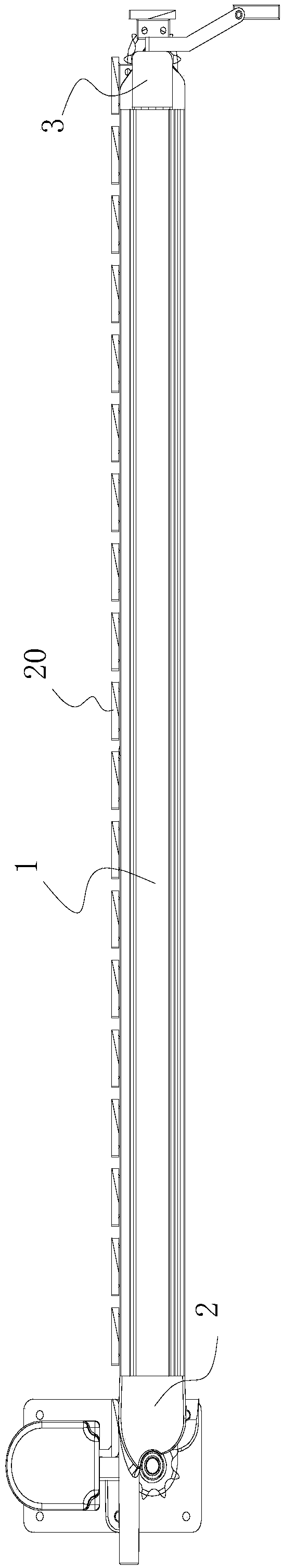
[0023] The load pallet is composed of a power component, a support component and a load component. The power assembly and the load assembly are installed on the support assembly.

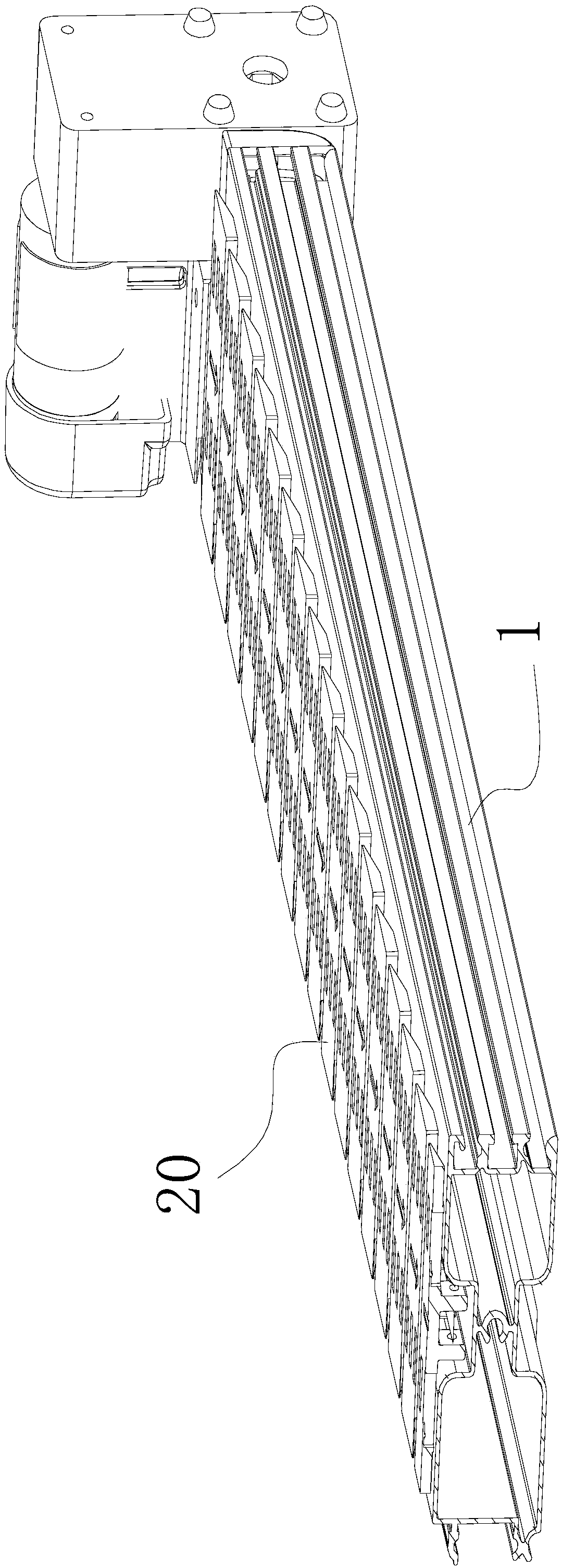
[0024] Such as figure 1 , 2 As shown, the support assembly includes a profile 1 , a driving end support 2 , and a driven end support 3 .

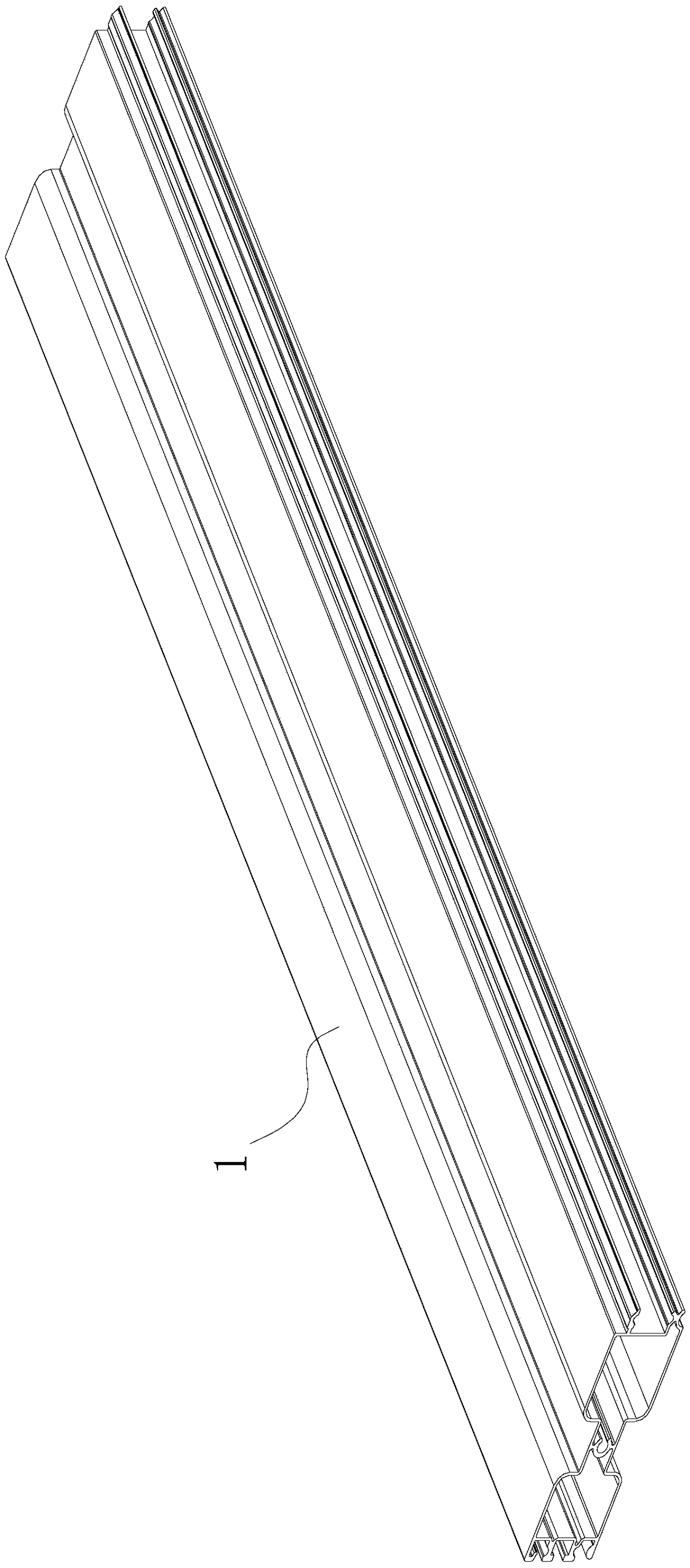
[0025] Such as image 3 , 4 As shown, the profile 1 has a straight and flat structure as a whole, with a cavity inside, except that both ends are open and present as an open structure, and other parts are a dense integral structure. The profile 1 is provided with two chute 4, one of which is located on the side of the profile 1 where one of the surfaces with the largest area and width is located, and the other chute 4 is located at the other surface of the profile 1 with the largest area and width On this side, the chute 4 on both sides is symmetrically distributed. An inlay structure and a receptor structure are respectively provided on the two surfaces of...


PUM


Abstract

The invention discloses a chain plate. The chain plate comprises a carrying part and clamping parts, the carrying part is of a flat cuboid structure, the clamping parts are also of a flat cuboid structure, the two clamping parts are arranged on one surface of the carrying part, are parallel, and are symmetrically distributed around the center line of the carrying part, and a guiding inclined faceI and a guiding inclined face II are arranged on the surface of the carrying part and have the effect that a low-resistance region is formed on the surface of the carrying part, the carrying part is promoted to rapidly respond to driving of a driving force on the region to be prior to other parts, accordingly, when the chain plate is driven, the same movement posture is kept all the time, and thechain plate is prevented from shaking.

Description

technical field [0001] The invention relates to a chain plate used on a loading pallet of an automatic vending machine. Background technique [0002] The structure of the vending machine is relatively simple, and its whole includes units such as a box body, a loading tray, refrigeration, connection and delivery, and code scanning. The loading pallet is a part for placing products. Inside the whole machine, the loading pallet is usually arranged in a stacked manner. The products on the loading pallet are arranged in a straight line in a front-to-back manner, and the products can be output one by one during the control of the operation of the loading pallet. According to the power transmission mode, the load pallet can be divided into active structure and passive structure; according to the transmission structure, it includes the handling structure and the push structure. The common loading pallet includes a loading pallet that drives the chain plate to carry the product. Th...

Claims


Application Information

Patent Timeline
Patent Type & Authority Applications(China)
IPC IPC(8): G07F11/00G07F11/16G07F11/24
CPCG07F11/16G07F11/007G07F11/24
Inventor 史正
Owner HANGZHOU ZHONGYA MACHINERY CO LTD
Why Eureka
Try Eureka