
Variable lateral force cavitator

A cavitation, lateral force technology, applied in the direction of hydrodynamic characteristics/hydrostatic characteristics, underwater operation equipment, ship construction, etc., can solve the problem of difficult implementation of control methods, and achieve simple structure and operability. strong effect

Inactive Publication Date: 2011-04-20
HARBIN ENG UNIV
View PDF0 Cites 0 Cited by
  • Summary
  • Abstract
  • Description
  • Claims
  • Application Information

AI Technical Summary

Problems solved by technology

In theory, the variable resistance cavitator can change the resistance of the vehicle body and the size of the cavitation relatively quickly. However, since the top of the cavitator concentrates the total pressure resistance of the entire supercavitating vehicle with a movement speed of 100 meters reduced to zero, in order to obtain Good control effect requires its control mechanism to provide hundreds of thousands of newtons of force, which is difficult to implement

Method used


Image

  • Variable lateral force cavitator
  • Variable lateral force cavitator
  • Variable lateral force cavitator

Examples


Embodiment Construction

[0018] The present invention is described in more detail below in conjunction with accompanying drawing example:

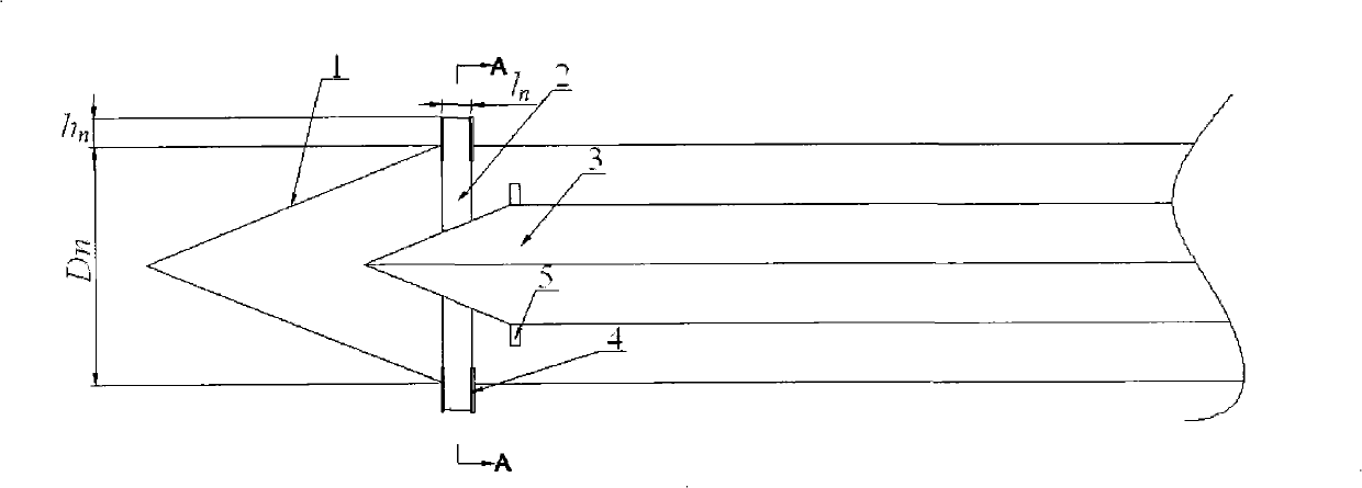
[0019] Referring to FIG. 1 , the composition of the variable lateral force cavitator of the present invention includes a front conical cavitator 1 , a control element 2 , a movable element 3 , a movable arc-shaped steel sheet 4 and an annular baffle 5 .

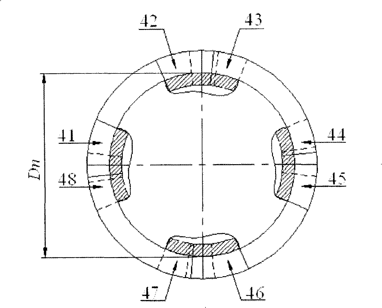
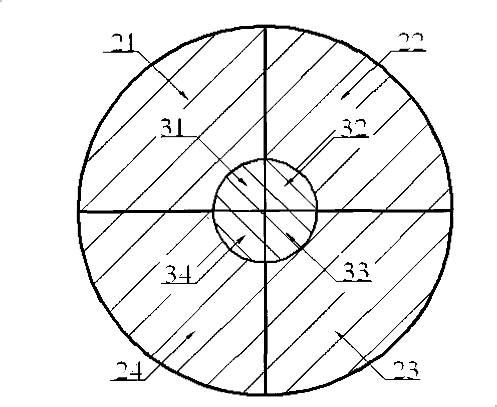
[0020] A movable element with a diameter smaller than Dn is installed in the front conical cavitator. The movable element is composed of a conical movable part and a cylindrical joystick. The four-lobe cylindrical joystick controls the lateral displacement of the four-lobe conical part respectively, thereby changing Circumferential displacement h of the control element n The value changes the effective working area of ​​the cavitator, and then changes the size of the cavitation. When the displacement of any two sides of the movable element is inconsistent, the control element has asymmetry, and the conical cavit...


PUM


Abstract

The invention provides a variable lateral force cavitator, which comprises a front-end tapered cavitator and a circular controlling element arranged behind the front-end tapered cavitator, wherein thecircular controlling element is divided into two to four lamellas; the joint of each lamella of the circular controlling element is provided with circular arc steel sheets mutually connected; the front-end tapered cavitator is internally provided with a movable element; the movable element consists of a tapered moving part and a cylindrical control stick; the tapered moving part and the cylindrical control lever are divided into lamellas of which the portion quantity is equal to that of the circular controlling element; and the cylindrical control lever controls the tapered part to transversely displace. The cavitator can control resistance coefficients and lift coefficients of the cavitator, can change the pitching force and the yawing force of navigating bodies, and has the advantages of strong maneuverability and simple structure.

Description

(1) Technical field [0001] The invention relates to an underwater motion device, in particular to a variable cavitator for adjusting the lateral force of an underwater vehicle. (2) Background technology [0002] In the traditional variable resistance cavitator, the supercavitation geometry and the drag coefficient of the cavitator can be obtained by changing the shape of the cavitator. In theory, the variable resistance cavitator can change the resistance of the vehicle body and the size of the cavitation relatively quickly. However, since the top of the cavitator concentrates the total pressure resistance of the entire supercavitating vehicle with a movement speed of 100 meters reduced to zero, in order to obtain A good control effect requires that the control mechanism can provide a force of hundreds of thousands of Newtons, and this control method is difficult to implement. (3) Contents of the invention [0003] The object of the present invention is to provide a varia...

Claims


Application Information

Patent Timeline
Patent Type & Authority Patents(China)
IPC IPC(8): B63G8/14B63B1/38
CPCY02T70/122Y02T70/10
Inventor 郜冶胡晓杨春英熊永亮
Owner HARBIN ENG UNIV
Learn More