Fluid container measurement system employing load cell linkage member

a technology of load cell and container, applied in the direction of instruments, diagnostic recording/measuring, optical detection, etc., can solve the problems of large process time and may have to be emptied of urine bags, and achieve the effect of avoiding strain, convenient dilution and easy dilution

Active Publication Date: 2018-06-12
ADAPTEC MEDICAL DEVICES LLC
View PDF150 Cites 6 Cited by
  • Summary
  • Abstract
  • Description
  • Claims
  • Application Information

AI Technical Summary

Benefits of technology

[0015]Further, in certain aspects disclosed herein, the load measurement assembly may include a tether support member interface configured to receive a tether support member. The tether support member is configured to support a tube from a fluid container so the tube is not strained to unduly impose a force placed on an installed load cell linkage member and thus the load cell. The load cell linkage member may be permanently installed on the load measurement assembly or provided as a load cell linkage member configured to be interconnected with a load cell interconnect of the load cell measurement assembly, including for example as described above. The tether support member is configured to support a predefined length of the tube with the load measurement assembly as part of the weight of the fluid container. The predefined length of the supported portion of the tube can be selected to provide slack in the supported portion of the tube when supported by the tether support member, so that a strain is avoided in the supported portion of the tube. Thus, a force from the load measurement assembly is not imparted on the fluid container from strain. Further, the tether support member may be designed such that a supported portion of the tube will be angled upward so that any fluid contained in the tube is not pooled inside the tube and will be more easily drained to the fluid container.
[0016]The tether support member also assists in maintaining the tube at a desired angular orientation to the fluid container such that fluid in the tube is more readily drained to the fluid container through gravity. The tether support member is configured to be secured to the tether support member interface. The tether support member may include an optional electrical interface that is configured to be electrically coupled to the measurement control circuit when the tether support member is installed in the tether support member interface. Thus, the measurement control circuit may be configured to detect when the tether support member is inserted in the tether support member interface. The measurement control circuit may be configured to not measure the force on the load cell if the tether support member is not detected as being inserted in the tether support member interface. The measurement control circuit may also be further configured to detect sudden changes in force on the load cell as an indication that a tube may have been removed from a tether support member when a tether support member was previously detected. In response, the measurement control circuit can be configured to re-calibrate when a tube is reattached to the tether support member.
[0017]In another aspect, the measurement control circuit is configured to mitigate any dynamic force transmitted by the tube to the load cell. To do so, in one example, the measurement control circuit is configured to maintain a baseline load measurement of the force on the load cell. Preliminarily, when the measurement control circuit obtains a load measurement from the load cell, the measurement control circuit uses the previous load measurement to determine whether there has been a sudden increase in weight and / or whether there has been a sudden decrease in weight, such as whether a user has removed the bag. If so, the measurement control circuit is configured to generate an alert, including an alert that can be perceived by a user. Otherwise, the measurement control circuit determines whether the load measurement is less than a difference between a previous baseline load measurement and a baseline reset threshold load measurement. If so, then the measurement control circuit is configured to set a new baseline load measurement equal to the load measurement from the load cell, thereby assuming that the measured decrease in load measurement is the result of the dynamic force transmitted from the fluid tube to the load cell. Then, if the load measurement is greater than the previous baseline load measurement plus a noise floor threshold load measurement, the measurement control circuit adds a difference between the load measurement and the previous baseline load measurement to a running total, and sets a new baseline load measurement equal to the load measurement. Accordingly, the measurement control circuit is able to keep a running total measurement while incorporating any dynamic force transmitted from the tube to the load cell. Accounting for this dynamic force prevents the dynamic force of the tube from affecting weight measurement accuracy of the fluid container measurement system, thereby increasing the accuracy of the system. For example, if this dynamic force was ignored or unaccounted for, then real volume increases within the bag may be completely or partially masked by dynamic forces exerted by the tube.

Problems solved by technology

Further, the urine bag may have to be emptied.
This process can take substantial time, and thus, the frequency of measuring urine output may be determined more by convenience of staff schedules rather than strict physiological reasons.

Method used


Image

  • Fluid container measurement system employing load cell linkage member
  • Fluid container measurement system employing load cell linkage member
  • Fluid container measurement system employing load cell linkage member

Examples


Embodiment Construction

[0053]With reference now to the drawing figures, several exemplary aspects of the present disclosure are described. The word “exemplary” is used herein to mean “serving as an example, instance, or illustration.” Any aspect described herein as “exemplary” is not necessarily to be construed as preferred or advantageous over other aspects.

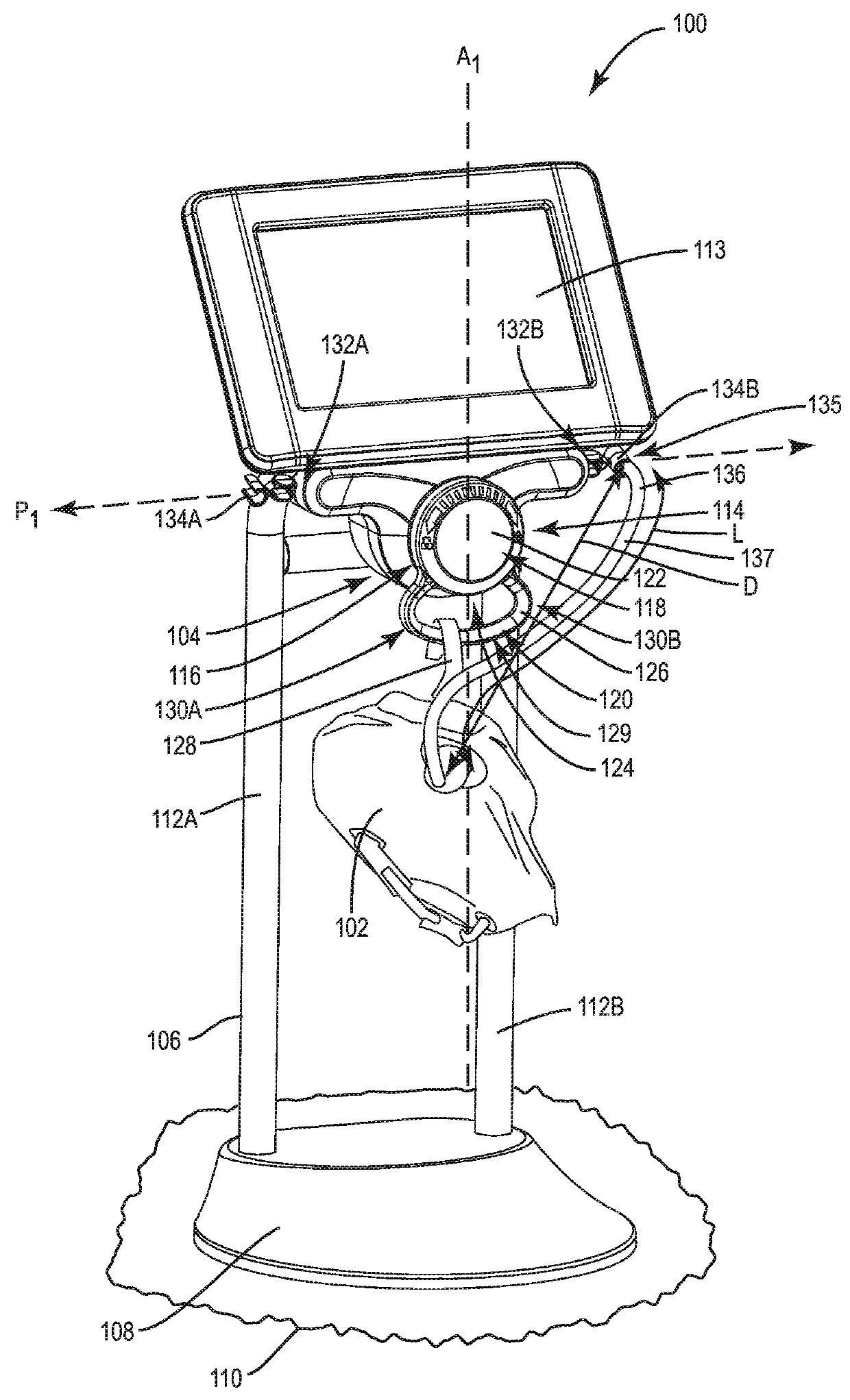
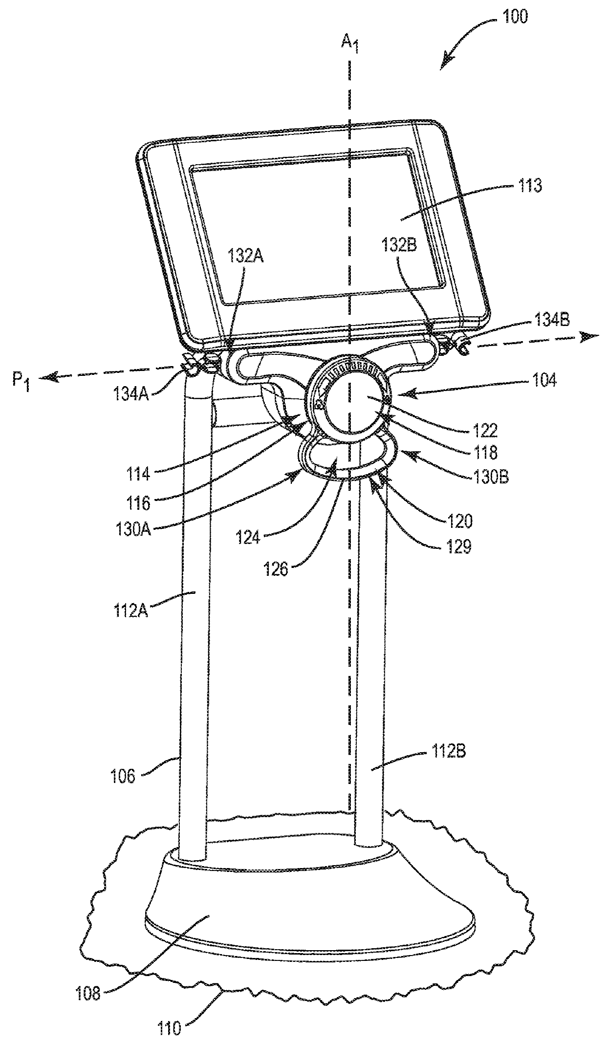
[0054]FIGS. 1A and 1B illustrate an exemplary fluid container measurement system 100 with a fluid container 102 installed thereon to be measured, and without a fluid container installed to be measured, respectively. As one example, the fluid container 102 may be a urine bag that is fluidly connected to a patient through a Foley catheter. The fluid container measurement system 100 includes a load measurement assembly 104 that is attached to a base assembly 106. The base assembly 106 includes a base 108 that is configured to rest on a support surface 110, such as a table or the floor. For example, it may be desired to place the base 108 on a table besid...


PUM

PropertyMeasurementUnit
angleaaaaaaaaaa
angleaaaaaaaaaa
angleaaaaaaaaaa

Abstract

A fluid container measurement system employing a load cell linkage member is disclosed. The fluid container measurement system is configured to suspend a load measurement assembly a distance above a support surface. The load measurement assembly houses a load cell and a measurement control circuit. The measurement control circuit is coupled to the load cell and configured to receive electrical signals indicative of a force imposed on the load cell. The load measurement assembly also includes or is configured to receive a load cell linkage member mechanically linked to the load cell. In this manner, a load placed on the load cell linkage member will be exerted on the load cell. Electrical signals generated by the load cell indicative of the force exerted on the load cell can be used to measure the fluid container attached to the load cell linkage member.

Description

PRIORITY APPLICATIONS[0001]The present application claims priority to U.S. Provisional Patent Application Ser. No. 62 / 335,939 filed on May 13, 2016 entitled “Fluid Container Measurement System Employing Load Cell Linkage Member,” the content of which is incorporated herein by reference in its entirety.[0002]The present application also claims priority to U.S. Provisional Patent Application Ser. No. 62 / 468,687 filed on Mar. 8, 2017 entitled “Fluid Container Measurement System Employing Load Cell Linkage Member,” the content of which is incorporated herein by reference in its entirety.BACKGROUND[0003]I. Field of the Disclosure[0004]The technology of the disclosure relates to monitoring fluid in a container, and more particularly to monitoring and measurement of a biomedical fluid, such as for example, urine collected in a fluid drainage container or bag from a patient using a urinary (Foley) catheter.[0005]II. Background[0006]In medical care settings such as hospitals and other medica...

Claims


Application Information

Patent Timeline
Patent Type & Authority Patents(United States)
IPC IPC(8): G01L1/00G01G17/04G01G19/18G01G19/14A61B5/20G01G21/23G01G23/36G01V8/10G08B21/18
CPCG01G19/14A61B5/208G01G17/04G01G19/18G01G23/36G01V8/10G08B21/18G01G21/23G16H40/63
Inventor PARKER, WALTER DANMUELLER, EDWARD JAMESGAUSMANN, KEITH HOBARTLUCK, NATHAN THOMASLIDDLE, SCOTT ERIC
Owner ADAPTEC MEDICAL DEVICES LLC
Why Eureka
Try Eureka