Flying robot with variable sweep angle launch tandem wings

A flying robot and variable technology, applied in aircraft, motor vehicles, wing adjustment and other directions, can solve the problem that the two rear folding wings 3 cannot be unfolded respectively, the front folding wings 2 cannot be unfolded separately, and the attitude control of the flying robot cannot be realized, etc. problems, to achieve the effect of facilitating high-speed flight, simplifying the folding structure and tail rudder structure, and light weight

Active Publication Date: 2017-02-22
HARBIN INST OF TECH
View PDF11 Cites 14 Cited by
  • Summary
  • Abstract
  • Description
  • Claims
  • Application Information

AI Technical Summary

Problems solved by technology

[0003] In order to solve the problem that the two front folding wings 2 and the two rear folding wings 3 of the existing ejection flying robot cannot be unfolded separately, and the attitude control of the flying robot cannot be realized, the present invention provides a variable grazing angle ejection string winged flying robot

Method used


Image

  • Flying robot with variable sweep angle launch tandem wings
  • Flying robot with variable sweep angle launch tandem wings
  • Flying robot with variable sweep angle launch tandem wings

Examples


specific Embodiment approach 1

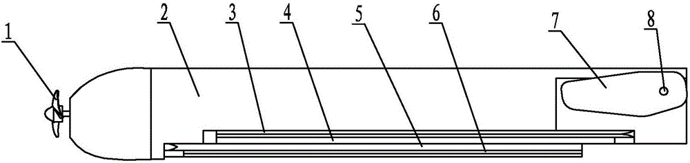
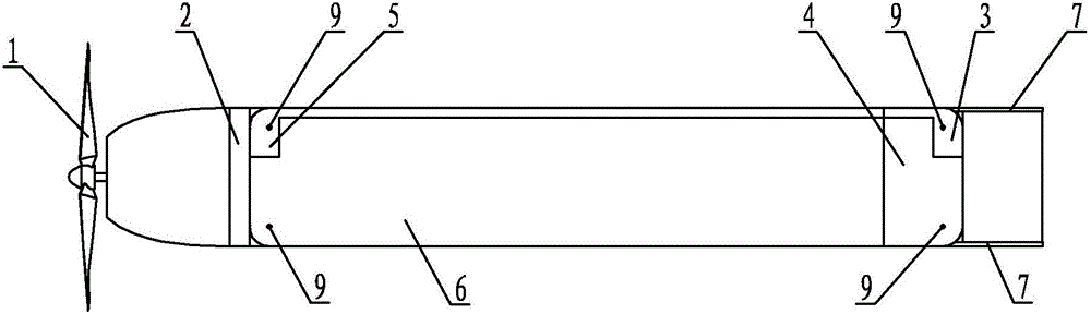
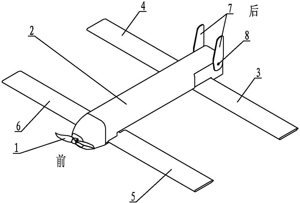
[0019] Specific implementation mode one: combine Figure 1 ~ Figure 4 Describe this embodiment, this embodiment comprises folding propeller 1, fuselage 2, left rear wing 3, right rear wing 4, left front wing 5, right front wing 6, two vertical empennages 7, two vertical empennage pin shafts 8 and four A rotating hinge 9, folding propeller 1 is installed on the head of fuselage 2, arranges like this to be conducive to the ejection launch of flying robot, left front wing 5 and right front wing 6 are symmetrically arranged on both sides of fuselage 2 front ends, left rear wing 3 and The right rear wing 4 is symmetrically arranged on both sides of the rear end of the fuselage 2, and the left front wing 5, the right front wing 6, the left rear wing 3 and the right rear wing 4 are respectively hinged with their corresponding rotary hinges 9, and each rotary hinge 9 is connected to the fuselage. 2. The corresponding steering gear is connected inside (the hinge 9 is driven by the stee...

specific Embodiment approach 2

[0021] Specific implementation mode two: combination Figure 4 The present embodiment will be described. The left front wing 5 and the right front wing 6 of the present embodiment are rotated forward by 0° to 90° from a position parallel to the fuselage 2 . Such an arrangement can ensure rapid and accurate deployment of the wings of the flying robot and that the front wings can only be swept back during flight, thereby reducing the complexity of the control of the flying robot. Other components and connections are the same as those in the first embodiment.

specific Embodiment approach 3

[0022] Specific implementation mode three: combination figure 2 The present embodiment will be described. The left rear wing 3 and the right rear wing 4 of the present embodiment are rotated backward by 0° to 90° from a position parallel to the fuselage 2 . This arrangement can ensure that the wings of the flying robot can be deployed quickly and accurately, and that the rear wing can only be swept forward during flight, thereby reducing the complexity of the control of the flying robot. Other components and connections are the same as those in the second embodiment.

[0023] Working principle of the present invention:

[0024] (1) Before the flying robot ejects and takes off, each wing rotates to a position parallel to the fuselage 2, see figure 1 and figure 2 ;

[0025] (2) After the flying robot is ejected, the left front wing 5 and the right front wing 6 are fully deployed after turning forward 90° under the driving of the steering gear; the left rear wing 3 and the ...


PUM


Abstract

The invention discloses a flying robot with variable sweep angle launch tandem wings and aims to solve the problem that neither two front folding wings nor two rear folding wings of an existing launch flying robot can be unfolded respectively, so that moving attitude control of the flying robot is limited. The flying robot comprises a folding propeller, a fuselage, a left rear wing, a right rear wing, a left front wing, a right front wing, two vertical tails, two vertical tail pin shafts and four rotary hinges, wherein the folding propeller is installed on the head of the fuselage, the left front wing and the right front wing are symmetrically arranged on the two sides of the front end of the fuselage, the left rear wing and the right rear wing are symmetrically arranged on the two sides of the rear end of the fuselage, the left front wing, the right front wing, the left rear wing and the right rear wing are hinged to the corresponding rotary hinges respectively, each rotary hinge is connected with a corresponding helm gear in the fuselage, and the two vertical tails are symmetrically arranged on the two sides of the tail end of the fuselage and installed on the upper surface of the tail portion of the fuselage through torsional springs. The flying robot is used for attitude control.

Description

technical field [0001] The invention relates to a catapult flying robot, in particular to a catapult tandem wing flying robot with variable grazing angle. Background technique [0002] At present, the catapult flying robot has been favored by the majority of researchers due to its high launch speed, good launch stability, and ability to launch in complex terrain. At the same time, the wings of the catapult flying robot can be folded, which is convenient for transportation and storage. Usually, the control method of flying robots is to use ailerons and tail rudders to realize its roll and pitch attitude control. However, due to the wing folding characteristics of catapult folding wing flying robots, this method will make the folding structure more complicated and the number of parts increase, the failure rate is also relatively high. At the same time, for the tandem wing layout, if two ailerons are used to control, the control force generated is small and the response speed ...

Claims


Application Information

Patent Timeline
Patent Type & Authority Applications(China)
IPC IPC(8): B64C3/40B64C39/08
CPCB64C3/40B64C39/08B64U10/25B64U70/70
Inventor 赵杰高良朱延河
Owner HARBIN INST OF TECH
Why Eureka
Try Eureka