Special micro motor fixing device

A technology of micro motors and fixing devices, applied in the direction of electromechanical devices, electrical components, electric components, etc., can solve the problems of no vibration reduction, loose fixing devices, single motor fixing methods, etc., and achieve the effect of reducing service life and avoiding loosening

Inactive Publication Date: 2019-03-08
贵州标准电机有限公司
View PDF10 Cites 4 Cited by
  • Summary
  • Abstract
  • Description
  • Claims
  • Application Information

AI Technical Summary

Problems solved by technology

With the development of the times and science and technology, the advancement of science and technology has also promoted the technological progress of special micro-motor fixtures, but there are still defects. The current special micro-motor fixtures have a relatively simple way of fixing the motor, and there is no structure for vibration reduction. , the vibration of the motor for a long time not only easily causes the loosening of the fixing device, but also affects the service life of the motor, so a special micro-motor fixing device is proposed to solve this problem

Method used


Image

  • Special micro motor fixing device
  • Special micro motor fixing device

Examples


Embodiment 1

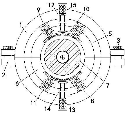
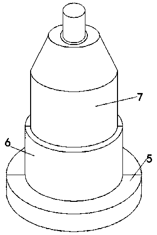
[0016] Embodiment 1: as figure 1 with figure 2 As shown, a special micro-motor fixing device includes two fixing covers 1, the left and right sides of the two fixing covers 1 are fixedly equipped with fixing blocks 2, and the two fixing blocks 2 on the same side are all connected by threaded threads. The rods 3 are fixedly connected, and the insides of the two fixed blocks 2 on the same side are provided with thread grooves matching the threaded rods 3, and the fixed blocks 2 are cuboid, and the inside of the fixed cover 1 is fixedly equipped with a base 5, and the front of the base 5 Mounting seat 6 is fixedly installed on the surface, both base 5 and mounting seat 6 are semi-cylindrical, and the combination of two bases 5 is a hollow cylinder, and the combination of two mounting seats 6 is a hollow cylinder. A motor 7 is installed in the room, and the model of the motor 7 can be 5IK90RGN. Two telescopic rods 8 are fixedly installed on the opposite surfaces of the two fixed...

Embodiment 2

[0017] Embodiment 2: as figure 1 with figure 2 As shown, a special micro-motor fixing device includes two fixed covers 1, the left and right sides of the two fixed covers 1 are fixed with fixed blocks 2, and the two fixed blocks 2 on the same side pass through The threaded rods 3 that are threaded are fixedly connected, the inside of the fixed cover 1 is fixedly installed with a base 5, the front surface of the base 5 is fixedly installed with a mounting base 6, and a motor 7 is movably installed between the two mounting bases 6 Two telescopic rods 8 are fixedly installed on the opposite surfaces of the two fixed covers 1, and the ends of the two telescopic rods 8 on the same side away from the fixed cover 1 are fixedly connected to the fixed sleeve 9, and the two telescopic rods 8 are fixedly connected to the fixed cover 9. The opposite surface of the fixed cover 9 is fixedly installed with a rubber cover 10 that is movably connected with the motor 7, and there are two spri...


PUM


Abstract

The invention relates to the technical field of motors, and discloses a special micro motor fixing device. The special micro motor fixing device comprise two fixing covers, wherein the left side and the right side of the two fixing covers are fixedly provided with fixing blocks respectively, and the two fixing blocks on the same side are fixedly connected through threaded rods which are in threaded connection; a base is fixedly arranged in each fixing cover; a mounting base is fixedly arranged on the front surface of each base; a motor is movably arranged between the two mounting bases; two telescopic rods are fixedly arranged on the two opposite surfaces of the two fixing covers; one ends, far away from the fixing covers, of the two telescopic rods at the same side are fixedly connected with fixing sleeves respectively; and rubber sleeves movably connected with the motors are fixedly arranged on the opposite surfaces of the two fixing sleeves. According to the special micro motor fixing device, shortening of the service life of the motor caused by looseness of the fixing device due to vibration of the motor is avoided, and the purpose of achieving the vibration reduction functionis realized by the special micro motor fixing device.

Description

technical field [0001] The invention relates to the technical field of motors, in particular to a special micro motor fixing device. Background technique [0002] Special motors are relative to the fuzzy concepts of traditional brushed DC motors and AC asynchronous motors. Traditionally, except for brushed DC motors and AC asynchronous motors, all motors are called special motors, and the motors that are not used in special occasions are special motors. . With the development of the times and science and technology, the advancement of science and technology has also promoted the technological progress of special micro-motor fixtures, but there are still defects. The current special micro-motor fixtures have a relatively simple way of fixing the motor, and there is no structure for vibration reduction. , The vibration of the motor for a long time not only easily causes the loosening of the fixing device, but also affects the service life of the motor, so a special micro-moto...

Claims


Application Information

Patent Timeline
Patent Type & Authority Applications(China)
IPC IPC(8): H02K5/24
CPCH02K5/24
Inventor 曾格刷
Owner 贵州标准电机有限公司
Why Eureka
Try Eureka