Drone control method and device, drone and core network device
A control method and control device technology, applied in traffic control systems, aircraft traffic control, control/regulation systems, etc., can solve problems such as management difficulties, unmanned aerial vehicles are not allowed to fly, and the relationship between difficult drones and no-fly areas , to achieve the effect of effective management
- Summary
- Abstract
- Description
- Claims
- Application Information
AI Technical Summary
Problems solved by technology
Method used
Image

Examples
Embodiment Construction
[0105] Reference will now be made in detail to the exemplary embodiments, examples of which are illustrated in the accompanying drawings. When the following description refers to the accompanying drawings, the same numerals in different drawings refer to the same or similar elements unless otherwise indicated. The implementations described in the following exemplary examples do not represent all implementations consistent with the present disclosure. Rather, they are merely examples of apparatuses and methods consistent with aspects of the present disclosure as recited in the appended claims.
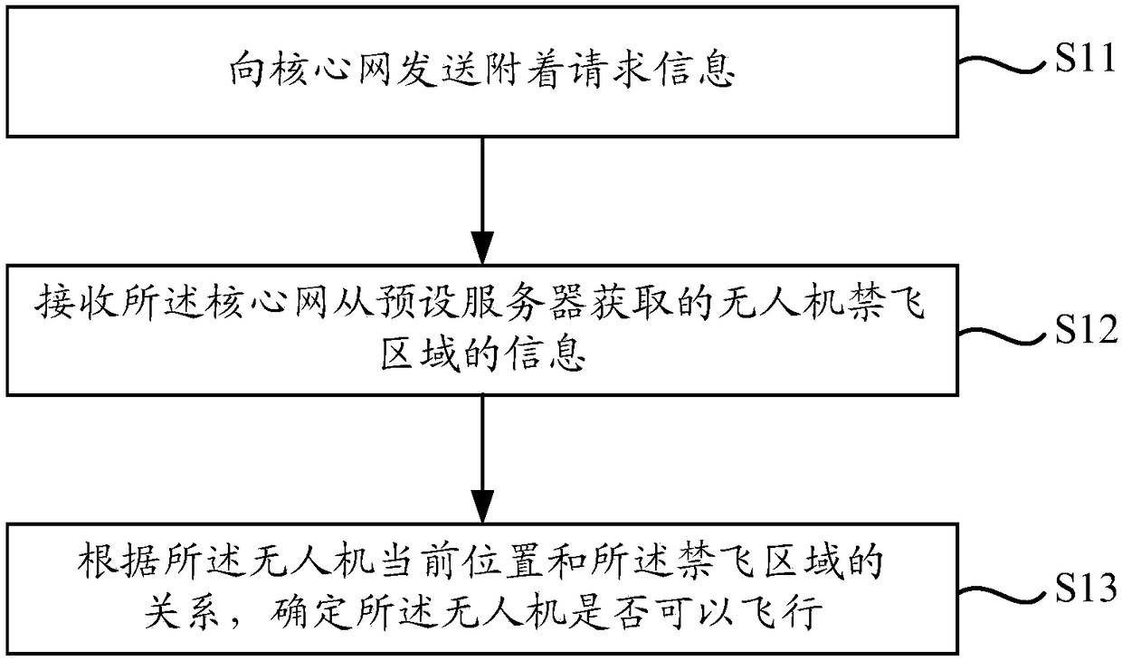
[0106] figure 1 It is a schematic flowchart of a drone control method shown according to an exemplary embodiment. The UAV control method described in this embodiment can be applied to UAVs, and the UAVs can access a core network corresponding to a cellular network through a base station. Such as figure 1 As shown, the UAV control method includes the following steps.
[0107] In ste...
PUM
 Abstract
Description
Claims
Application Information
PatSnap Eureka turns technology decisions into work you can execute. Powered by our Innovation Knowledge Graph, it runs expert workflows across engineering, life sciences, materials and intellectual property. Get your review-ready output in minutes.


