
Transient electromagnetic instrument and compensation algorithm

A transient electromagnetic and instrument technology, applied in the field of geophysical exploration, can solve the problem of weakening the secondary field strength and achieve the effect of improving sensitivity

Pending Publication Date: 2019-03-15
国科(重庆)仪器有限公司
View PDF1 Cites 17 Cited by
  • Summary
  • Abstract
  • Description
  • Claims
  • Application Information

AI Technical Summary

Problems solved by technology

201410092714.X's "A Transient Electromagnetic Measuring Device and Method" (hereinafter referred to as the "previous case") mentions the use of zeroing antenna coils to eliminate the influence of the primary field. However, this method eliminates the primary field while eliminating It also greatly weakens the strength of the secondary field

Method used


Image

  • Transient electromagnetic instrument and compensation algorithm
  • Transient electromagnetic instrument and compensation algorithm
  • Transient electromagnetic instrument and compensation algorithm

Examples


Embodiment 1

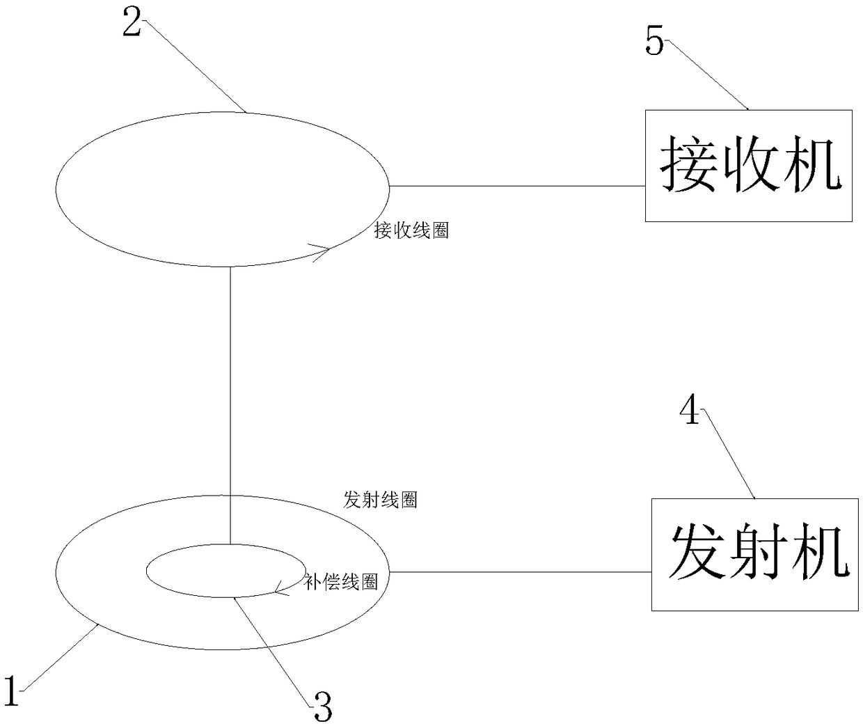
[0025] Embodiment 1: as figure 1 As shown, a transient electromagnetic instrument comprises a transmitter 4, a transmitting coil 1, a compensation coil 3, a receiving coil 2 and a receiver 5, and the centers of the transmitting coil 1, the compensation coil 3 and the receiving coil 2 are coaxial and mutually Parallel, the transmitting coil 1 and the receiving coil 2 have the same diameter; the receiving coil 2 is directly above the compensating coil 3 and the transmitting coil 1. In this embodiment, the center distance between the receiving coil 2 and the transmitting coil 1 is 0.5-4 times the diameter of the transmitting coil 1 . The transmitting coil 1 is closest to the detection area, the diameter of the compensation coil 3 is smaller than that of the transmitting coil 1 and the compensation coil 3 and the transmitting coil 1 are on the same horizontal plane. The wire type of the compensation coil 3 and the receiving coil 2 is the same, the compensation coil 3 is connected...

Embodiment 2

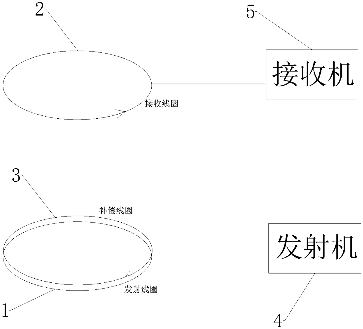
[0027] Embodiment 2: as figure 2 As shown, a transient electromagnetic instrument comprises a transmitter 4, a transmitting coil 1, a compensation coil 3, a receiving coil 2 and a receiver 5, and the centers of the transmitting coil 1, the compensation coil 3 and the receiving coil 2 are coaxial and mutually Parallel, the transmitting coil 1 and the receiving coil 2 have the same diameter; the receiving coil 2 is directly above the compensating coil 3 and the transmitting coil 1. In this embodiment, the center distance between the receiving coil 2 and the transmitting coil 1 is 0.5-4 times the diameter of the transmitting coil 1 . The transmitting coil 1 is closest to the detection area, and the compensation coil 3 has the same diameter as the transmitting coil 1 and is arranged above the transmitting coil 1 and close to the transmitting coil 1 but not overlapped with the transmitting coil 1 . The wire type of the compensation coil 3 and the receiving coil 2 is the same, the...


PUM


Abstract

The invention discloses a transient electromagnetic instrument. The transient electromagnetic instrument comprises a transmitter, a transmitting coil, a compensation coil, a receiving coil and a receiver, wherein the transmitting coil, the compensation coil and the receiving coil are coaxial and parallel to one another, and the diameter of the transmitting coil and the diameter of the receiving coil are the same; the compensation coil and the receiving coil are connected in series and opposite in winding direction, and the receiving coil is located over the compensation coil and the transmitting coil, so that the magnetic flux of a primary field generated by the transmitting coil penetrating through a compensation coil and receiving coil combination is equal to 0 or close to 0 all the time. The invention also discloses a compensation algorithm of the transient electromagnetic instrument. The influence of the primary field can be eliminated under the condition that a secondary field isnot weakened, early-stage signals of the secondary field are received, the signal dynamic range of the secondary field is enlarged, and the receiving accuracy is improved.

Description

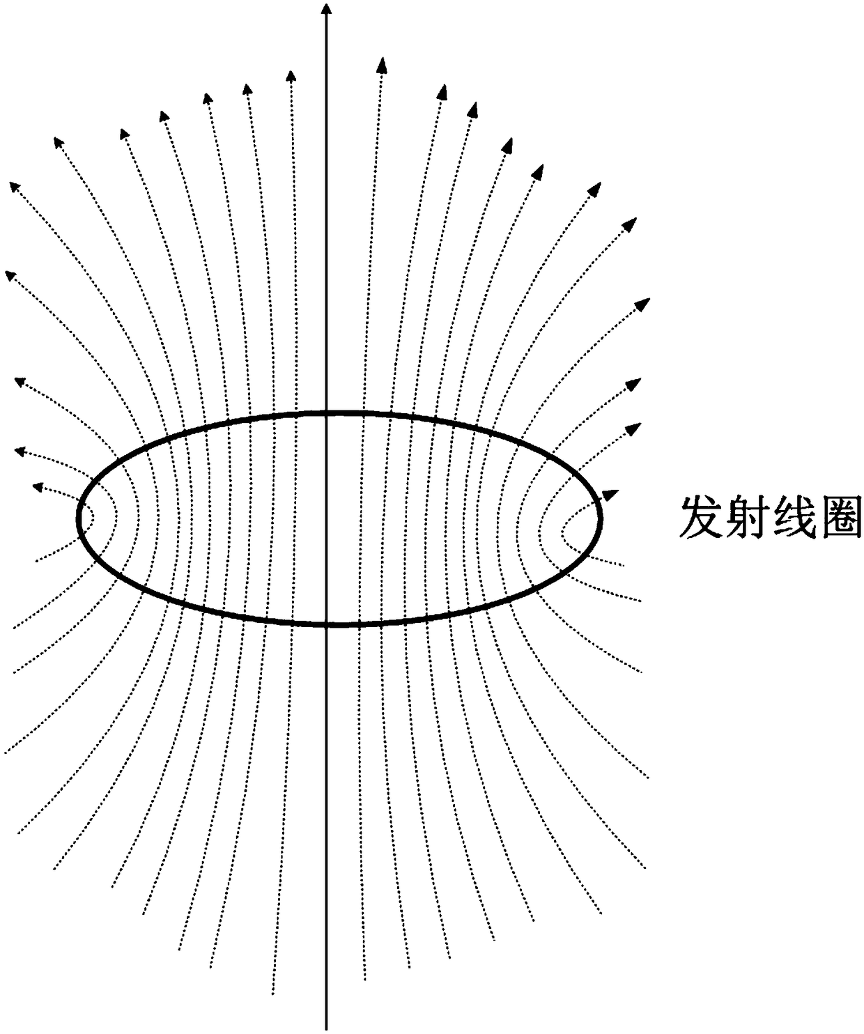
technical field [0001] The invention relates to the field of geophysical exploration, in particular to a transient electromagnetic instrument and a compensation algorithm. Background technique [0002] The transient electromagnetic method is a very important method in the field of geophysical exploration. It is a method of transmitting a pulsed electromagnetic field underground by using an ungrounded return line or a grounded line source, and observing the underground eddy current field between pulses. At present, the transient electromagnetic The most common receiving method is to use an induction coil to measure the rate of change of the magnetic field. When the transmitting current is turned off, the receiving coil itself generates an induced electromotive force, which is superimposed on the induced electromotive force generated by the underground eddy current field, thus causing an early rise signal in the transient electromagnetic field measurement. Distortion, forming ...

Claims


Application Information

Patent Timeline
IPC IPC(8): G01V3/10G01V3/38
CPCG01V3/10G01V3/38
Inventor 陈健马磊
Owner 国科(重庆)仪器有限公司
Learn More