Susceptor for wafer

A chip and base technology, applied in discharge tubes, electrical components, circuits, etc., can solve problems such as inability to ensure insulation

Active Publication Date: 2019-03-15
NGK INSULATORS LTD
View PDF7 Cites 2 Cited by
  • Summary
  • Abstract
  • Description
  • Claims
  • Application Information

AI Technical Summary

Problems solved by technology

If there is a gap between the insulating tube and the penetration part of the cooling plate, there is a problem that the gap becomes a conduction path and the insulation cannot be ensured.

Method used


Image

  • Susceptor for wafer
  • Susceptor for wafer
  • Susceptor for wafer

Examples


Embodiment Construction

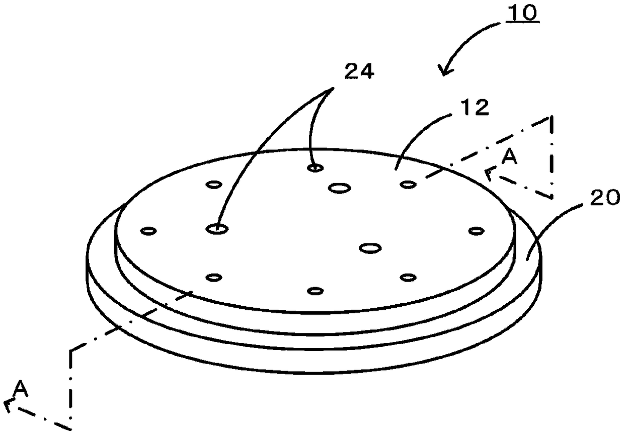
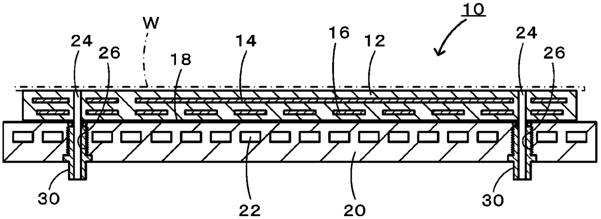
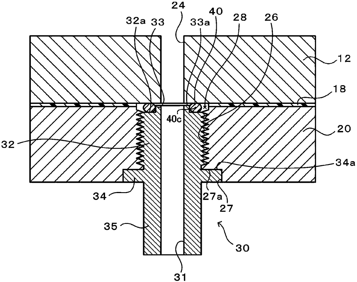
[0028] Embodiments of the present invention will be described based on the drawings. figure 1 It is a perspective view of an electrostatic chuck 10 as an example of the wafer susceptor of the present invention, figure 2 yes figure 1 The A-A sectional view of image 3 yes figure 2 An enlarged view of the periphery of the insulating tube 30, Figure 4 is an enlarged perspective view of the annular protrusion 33, Figure 5 It is a sectional view showing how the insulating tube 30 is attached to the screw hole 26 . In addition, in image 3 and Figure 5 In the figure, the electrostatic electrode 14, the resistance heating element 16, and the refrigerant passage 22 are omitted.

[0029] The electrostatic chuck 10 includes a flat plate 12, a cooling plate 20, a plurality of through holes 24, and an insulating tube 30 inserted into and fixed to each of the through holes 24 (refer to figure 2 , image 3 ), the upper surface of the flat plate 12 serves as a mounting surface...


PUM


Abstract

In an insulating pipe 30, an abutment surface 34a of the insulating pipe 30 abuts on a stopper surface 27a of a cooling plate 20. Thus, the insulating pipe 30 is blocked from further intruding into ascrew hole 26, the end surface 33a of an annular projection 33 of the insulating pipe 30 is positioned at a prescribed position that is not in contact with a plate 12, and an O ring 40 is deformed bya prescribed amount by being compressed between a stepped surface 32a of the insulating pipe 30 and the lower surface of the plate 12.

Description

technical field [0001] The present invention relates to a wafer susceptor used in semiconductor manufacturing equipment. Background technique [0002] As wafer susceptors used in semiconductor manufacturing equipment, electrostatic chucks, vacuum chucks, and the like are known. For example, the electrostatic chuck described in Patent Document 1 is formed by bonding a flat plate made of ceramics embedded with electrodes that generate electrostatic attraction force to a cooling plate made of metal via a resin layer, and has a through hole penetrating the flat plate and the cooling plate. . The through holes are used for insertion of lift pins for lifting a wafer placed on the plate, or for supplying gas between the back surface of the wafer and the plate. An insulating tube is inserted into a portion of the through hole that penetrates the cooling plate (cooling plate penetration portion). The insulating tube is bonded to the cooling plate with an adhesive interposed betwee...

Claims


Application Information

Patent Timeline
Patent Type & Authority Applications(China)
IPC IPC(8): H01L21/683
CPCH01L21/67109H01L21/67126H01L21/6831H01L21/6838H01L21/68757H01L21/68785H01J37/32431H01L21/67103H01L21/6833H01L21/68714H01L21/302
Inventor 久野达也渡边玲雄
Owner NGK INSULATORS LTD
Why Eureka
Try Eureka