
Feedthrough device

A technology of feedthrough and main body, which is applied in the field of sealed electric feedthrough devices, and can solve problems such as increasing pressure and increasing temperature

Inactive Publication Date: 2019-03-15
ENERGIZER BRANDS
View PDF4 Cites 0 Cited by
  • Summary
  • Abstract
  • Description
  • Claims
  • Application Information

AI Technical Summary

Problems solved by technology

Thus, in some applications, the feedthrough may experience harsh environments on at least one side of the wall through which it extends (e.g., the feedthrough may be exposed to corrosive substances, increased pressure, and / or elevated temperature)

Method used


Image

  • Feedthrough device
  • Feedthrough device
  • Feedthrough device

Examples


Embodiment Construction

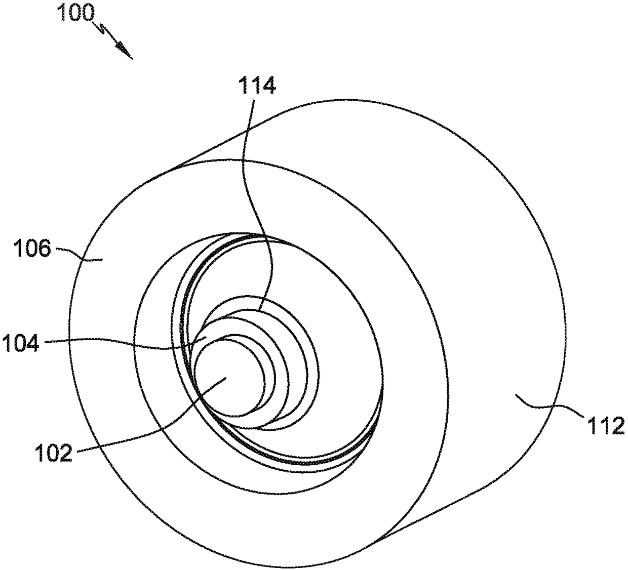
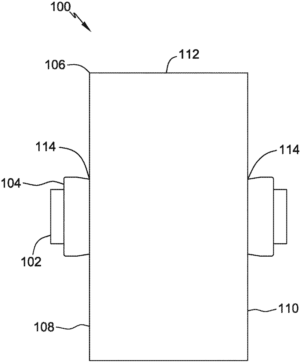
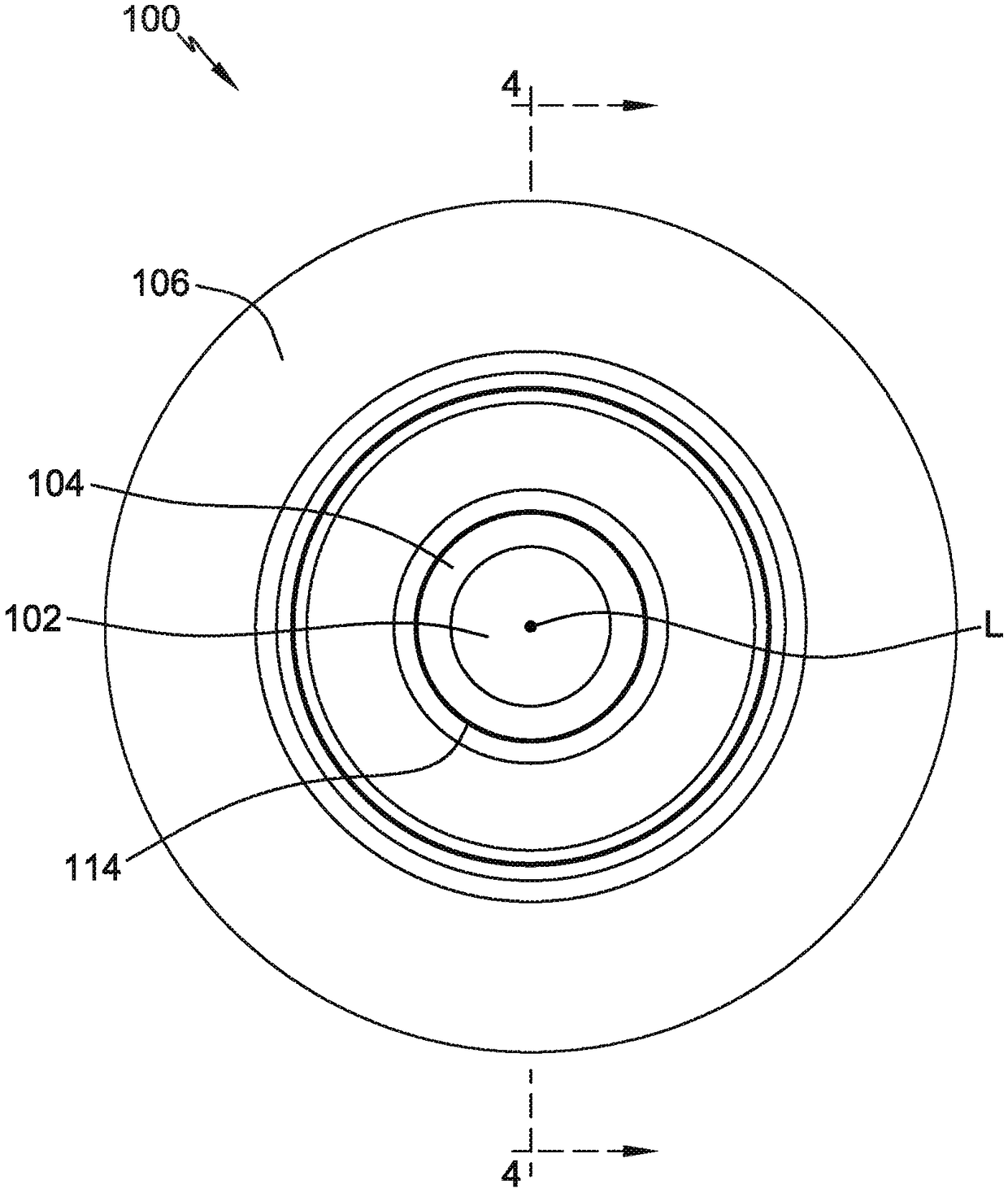
[0027] Referring now to the accompanying drawings, in particular Figure 1-3 , a feedthrough device according to an embodiment is generally indicated by reference numeral 100 . The feedthrough 100 includes a conductor 102 , an insulator 104 surrounding at least a portion of the conductor 102 , and a body 106 surrounding at least a portion of the insulator 104 . In some embodiments, conductor 102 is an electrical conductor. In some embodiments, conductor 102 is a thermal conductor.

[0028] In the illustrated embodiment, the body 106 is all or a portion of a wall of a sealed housing, such as an end wall of a lithium battery cell housing. The body 106 has a longitudinal end face, referred to herein as a first face 108 (eg, the outer surface of the battery cell housing) and a second face 110 (eg, the inner surface of the battery cell housing) longitudinally spaced from the first face 108 . ). A third face (eg, laterally outer surface) 112 extends longitudinally between first ...


PUM


Abstract

A feedthrough device includes a body having longitudinally spaced first and second end faces and an inner surface defining an opening extending longitudinally through the body, a conductor extending within the opening of the body, and an insulator extending within the opening of the body transversely intermediate the conductor and the inner surface of the body to insulate the conductor from the body, wherein the conductor includes an interior portion surrounded by the insulator and an exterior portion extending beyond the insulator, the exterior portion having a diameter that is greater than adiameter of the interior portion.

Description

[0001] Cross references to related patent applications [0002] This application claims priority to US Patent Application 62 / 276,649, filed January 8, 2016, the entire contents of which are incorporated herein by reference. This application is related to U.S. Patent Application 14 / 192558, filed February 27, 2014, which claims priority to U.S. Patent Application 61 / 777,777, filed March 12, 2013, both by This reference is incorporated herein in its entirety. technical field [0003] The present invention relates generally to a feedthrough device, and more particularly to a sealed electrical feedthrough device. Background technique [0004] A feedthrough is an electrical device used to transmit electrical power through a wall, typically the wall of a hermetic enclosure. For example, in some cases feedthroughs may be utilized to transmit power through the walls of electrochemical housings (e.g., terminals extending into a battery), walls of heating housings (e.g., thermocouple...

Claims


Application Information

Patent Timeline
IPC IPC(8): H01M2/06H01M50/172
CPCA61N1/3754H02G3/22H01G4/232H01G4/236H01G9/008H01G9/10H01G4/35Y02E60/10H01M50/172
Inventor W·C·布尚G·J·戴维松T·W·古力S·L·威斯克
Owner ENERGIZER BRANDS
Learn More