Reference signal tracking in a wireless communication system

A wireless communication system and reference signal technology, applied in the field of reference signal tracking in wireless communication systems, can solve the problem of not providing a robust management mechanism

Active Publication Date: 2019-03-15
TELEFON AB LM ERICSSON (PUBL)
View PDF3 Cites 3 Cited by
  • Summary
  • Abstract
  • Description
  • Claims
  • Application Information

AI Technical Summary

Problems solved by technology

[0013] Known implementations of analog beamforming in wireless communication networks do not provide mechanisms for robust management of network and UE beams

Method used


Image

  • Reference signal tracking in a wireless communication system
  • Reference signal tracking in a wireless communication system
  • Reference signal tracking in a wireless communication system

Examples


Embodiment Construction

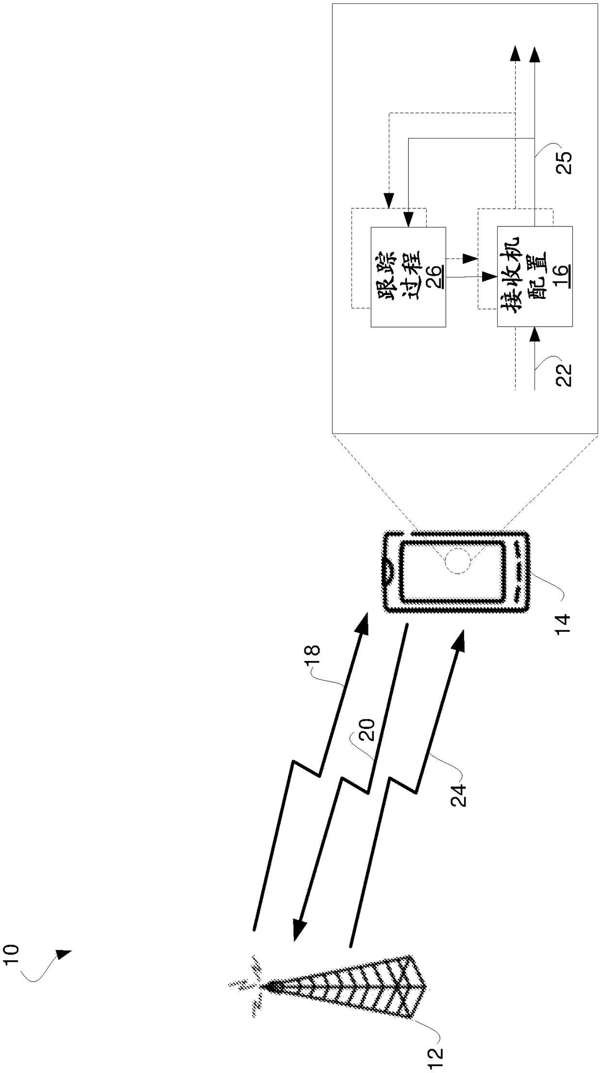
[0067] figure 1 A wireless communication system 10 is shown in accordance with one or more embodiments. System 10 includes network equipment 12, illustrated as a base station. System 10 also includes a wireless device 14, such as user equipment (UE). Network device 12 is configured to transmit wireless signals to and receive wireless signals from wireless device 14 .

[0068] In this regard, the wireless device 14 has one or more receiver configurations 16, each tuneable for wireless signal reception. Tuned in a certain manner, for example, receiver configuration 16 may employ a particular antenna array, beamformer, digital processing chain, and / or other physical resources. If tuned differently, the same receiver configuration 16 may configure those same physical resources differently and / or use one or more different antenna arrays, beamformers, digital processing chains and / or different physical resources. In one particular example, for example, wireless device 14 may use...


PUM


Abstract

A wireless device (14) is configured to receive, from network equipment (12), a tracking process base signal (18) using a receiver configuration (16) with tunable beamforming, and transmit a report (20) to the network equipment (12) indicating reception of the tracking process base signal (18). The wireless device (14) is further configured to, responsive to transmitting the report (20), configurethe wireless device (14) with a tracking process (26) for the wireless device (14) to track a reference signal (24) by tuning the receiver configuration (16) with which the wireless device (14) received the tracking process base signal (18). The wireless device (14) is also configured to, based on receiving a reference signal (24) identified as being a reference signal (24) to be tracked by the tracking process (26), track the reference signal (24) by tuning beamforming of the receiver configuration (16).

Description

[0001] related application [0002] This application claims priority to US Provisional Patent Application Serial No. 62 / 342,732, filed May 27, 2016, which is hereby incorporated by reference in its entirety. Background technique [0003] Many implementations of 5G base stations are expected to utilize so-called analog beamforming. This is due to the higher complexity (mainly from a hardware perspective) of implementing so-called digital beamforming. The latter imposes fewer functional restrictions, but is much more expensive to implement. [0004] As used herein, "beamforming" means that a transmitter can amplify transmitted signal power in selected directions while suppressing transmitted signal power in other directions. Accordingly, the receiver can amplify signals received from selected directions while attenuating unwanted signals in other directions. In this context, analog beamforming means that beamforming can only be applied in one direction or a limited set of dir...

Claims


Application Information

Patent Timeline
IPC IPC(8): H04B7/06H04B7/08
CPCH04B7/0617H04B7/0626H04B7/063H04B7/0639H04B7/0695H04B7/088H04L25/0224H04B7/0417
Inventor J·弗鲁斯考格N·维贝里H·安德松J·卡莱达尔M·弗伦内张强
Owner TELEFON AB LM ERICSSON (PUBL)
Why Eureka
Try Eureka