Apparatus and method for determining beam in wireless communication system

a wireless communication system and beam technology, applied in wireless communication, wireless commuication services, site diversity, etc., can solve the problems of large overhead, large time and great complexity to determine the optimal transmit beam and the optimal receive beam, and achieve the effect of low complexity

Active Publication Date: 2015-09-10
SAMSUNG ELECTRONICS CO LTD +1
View PDF21 Cites 148 Cited by
  • Summary
  • Abstract
  • Description
  • Claims
  • Application Information

AI Technical Summary

Problems solved by technology

However, since the BS supports a plurality of transmit beam directions and a plurality of receive beam directions of the MS, it takes a great time and great complexity to determine an optimal transmit beam and an optimal receive beam.
When the optimal transmit / receive beams change, control information required to re-determine the optimal transmit / receive beams cause considerable overhead.

Method used


Image

  • Apparatus and method for determining beam in wireless communication system
  • Apparatus and method for determining beam in wireless communication system
  • Apparatus and method for determining beam in wireless communication system

Examples


Embodiment Construction

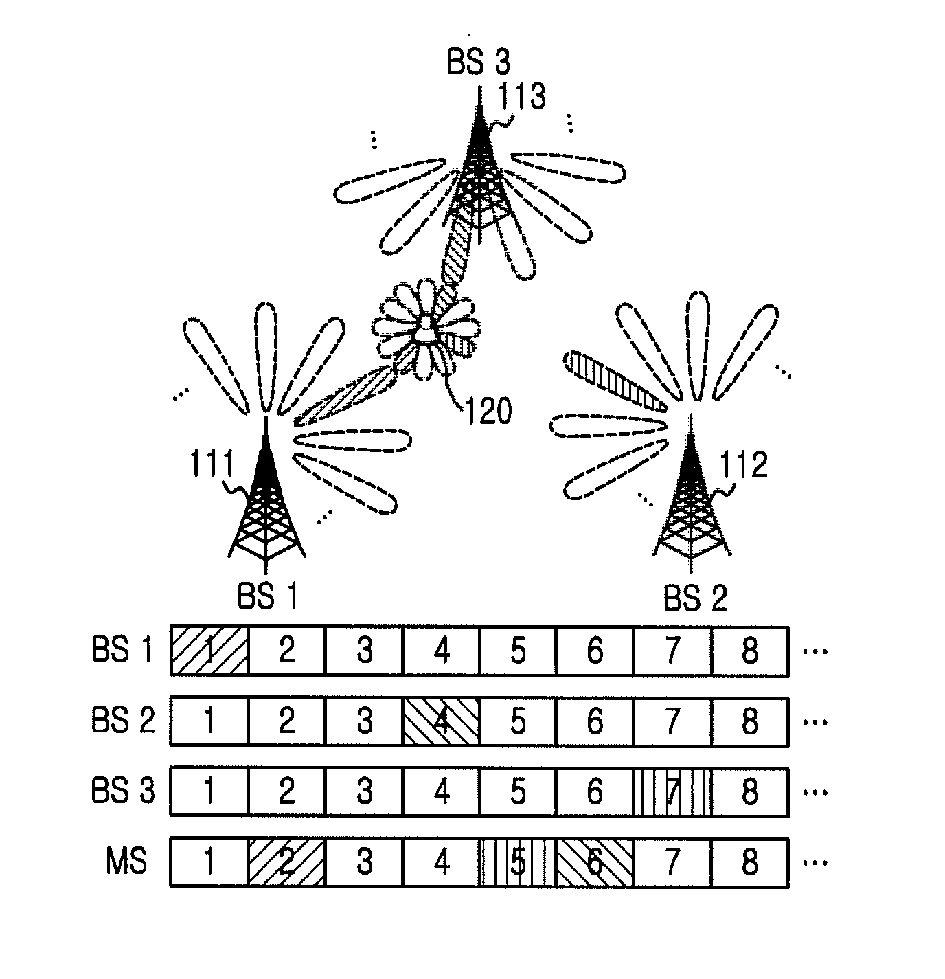
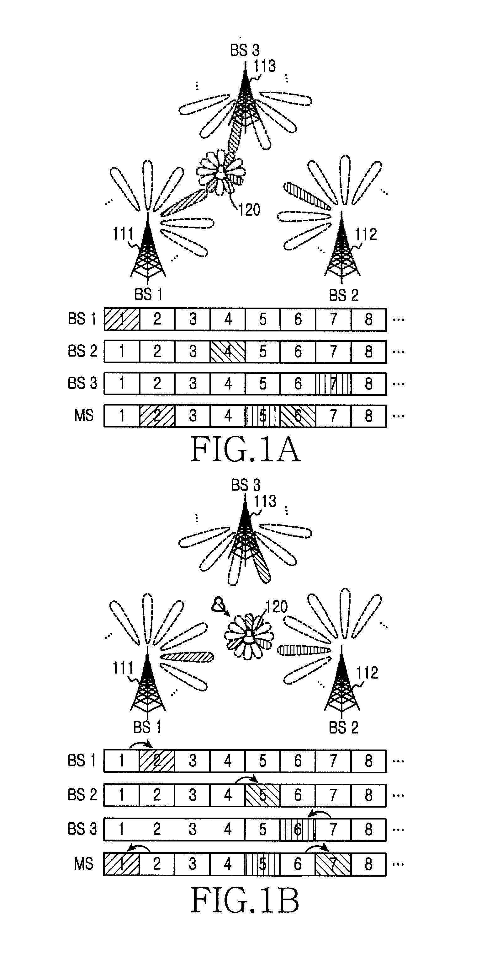
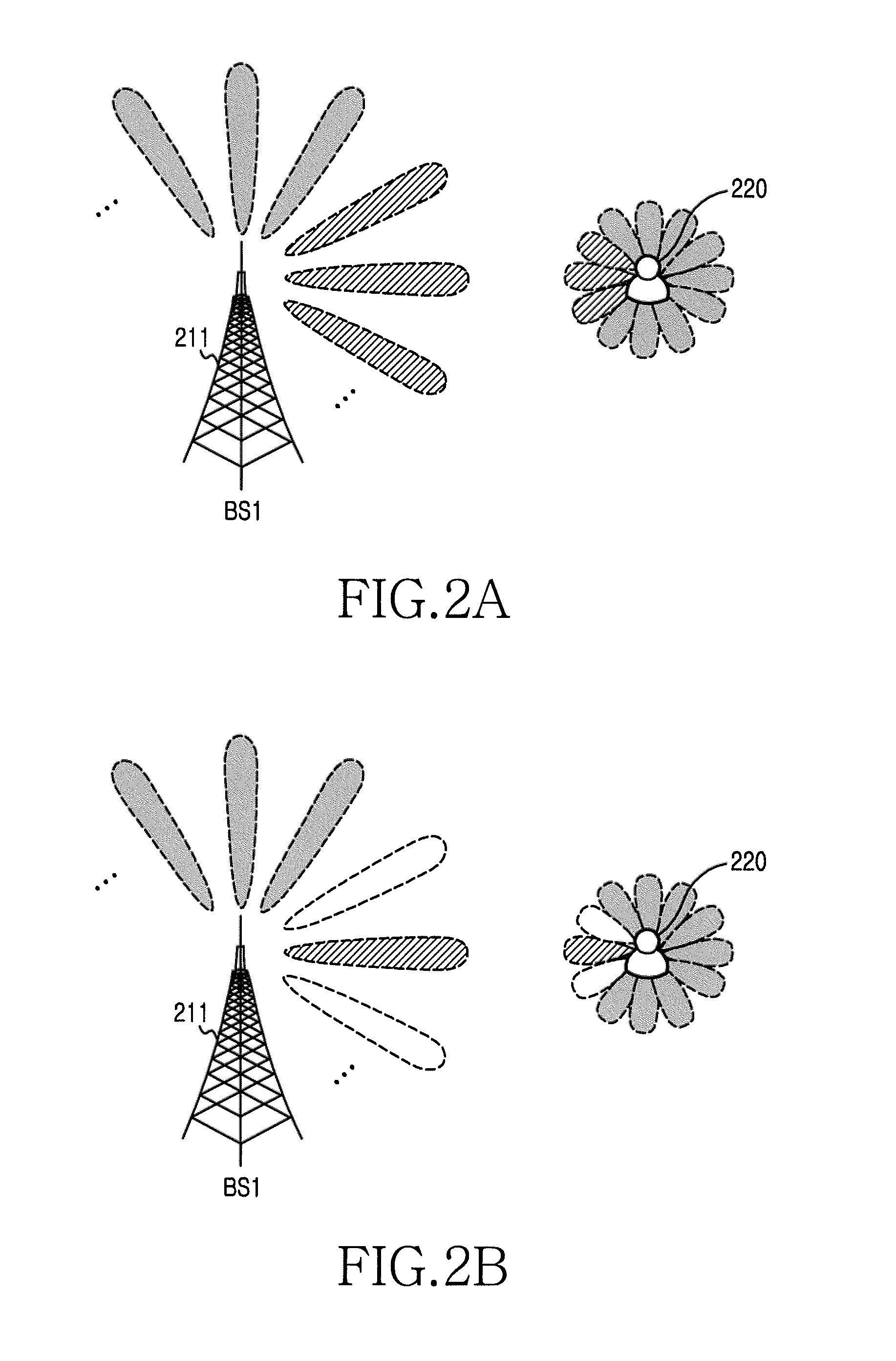
[0040]FIGS. 1A through 25, discussed below, and the various embodiments used to describe the principles of the present disclosure in this patent document are by way of illustration only and should not be construed in any way to limit the scope of the disclosure. Those skilled in the art will understand that the principles of the present disclosure may be implemented in any suitably arranged electronic device and communication system. The following description with reference to the accompanying drawings is provided to assist in a comprehensive understanding of exemplary embodiments of the invention as defined by the claims and their equivalents. It includes various specific details to assist in that understanding but these are to be regarded as merely exemplary. Accordingly, those of ordinary skill in the art will recognize that various changes and modifications of the embodiments described herein may be made without departing from the scope and spirit of the invention. In addition, ...


PUM


Abstract

A method to operate a receiving node is provided. The method includes receiving a first set of reference signals being transmit-beamformed using transmit beam groups in at least one transmitting node with receive-beamforming using receive beam groups. The method also includes transmitting information to select one transmit beam group of the transmit beam groups to one of the at least one transmitting node. The method further includes receiving a second set of the reference signals being transmit-beamformed using transmit beams of the one of the transmit beam groups in the at least one transmitting node with receive-beamforming using receive beams of one of the receive beam groups.

Description

CROSS-REFERENCE TO RELATED APPLICATION(S) AND CLAIM OF PRIORITY[0001]The present application is related to and claims the benefit under 35 U.S.C. §119(a) to a Korean patent application filed in the Korean Intellectual Property Office on Mar. 10, 2014, and assigned Serial No. 10-2014-0027593, the entire disclosure of which is hereby incorporated by reference.TECHNICAL FIELD OF THE INVENTION[0002]The present disclosure relates generally to beamforming in a wireless communication system.BACKGROUND OF THE INVENTION[0003]Future mobile communications are expected to demand a higher data rate and a greater capacity as mobile devices remarkably change and sharply increase in number. Hence, millimeter wave (mmWave) is used between a Base Station (BS) and a Mobile Station (MS), and beamforming for efficient signal transmission and reception in the mmWave are under consideration.[0004]The BS and the MS selects an optimal beam using beam scanning. However, since the BS supports a plurality of t...

Claims


Application Information

Patent Timeline
Patent Type & Authority Applications(United States)
IPC IPC(8): H04W36/30H04L5/00H04W36/00H04B7/04H04B7/06
CPCH04W36/30H04B7/0408H04L5/0048H04W36/0094H04B7/0617H04B7/024H04L5/0023H04L5/0035H04W36/06
Inventor PARK, SUNG JINKIM, MIN HOECHO, DONG HORYOO, SUN-HEUI
Owner SAMSUNG ELECTRONICS CO LTD
Why Eureka
Try Eureka