
Apparatus and method for beam locking in wireless communication system

apparatus technology, applied in the field of apparatus and a beam locking method in a wireless communication system, can solve the problems of reducing the serviceable area of the device, affecting the service life of the device,

Active Publication Date: 2013-02-14
SAMSUNG ELECTRONICS CO LTD
View PDF19 Cites 143 Cited by
  • Summary
  • Abstract
  • Description
  • Claims
  • Application Information

AI Technical Summary

Benefits of technology

The present invention provides a way to keep a user's beam direction in a wireless communication system. This helps to improve the quality of the signal and make the communication more reliable.

Problems solved by technology

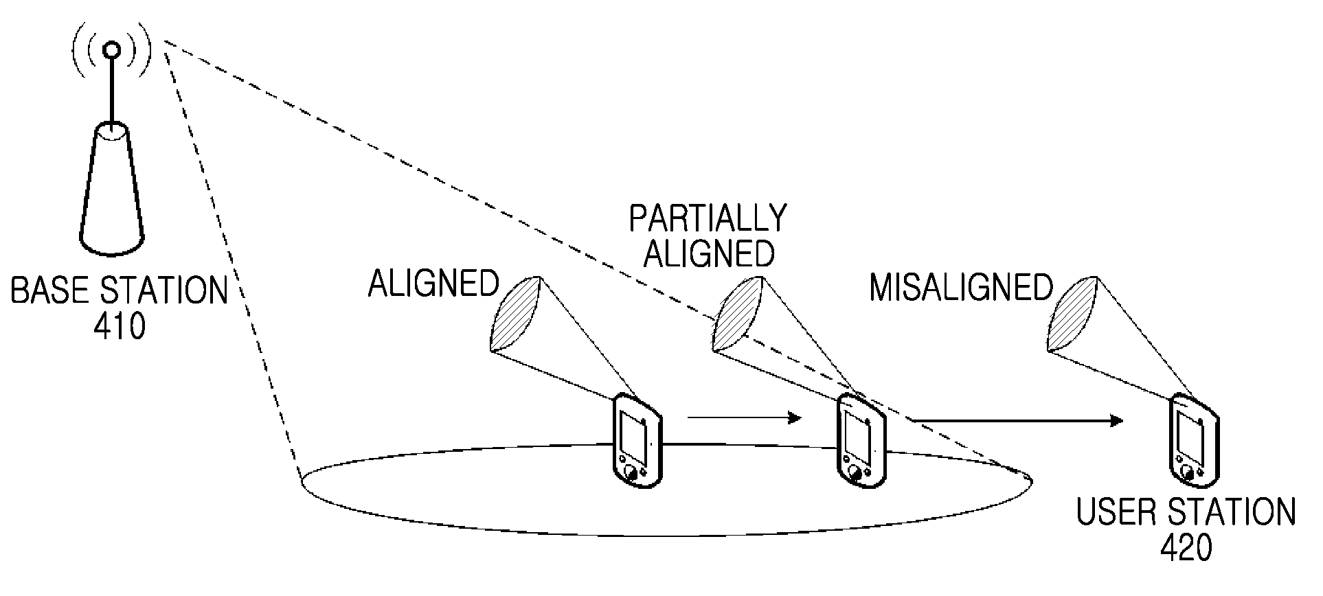
The technical problem addressed in this patent is the misalignment of beam directions between a base station and a user station due to the motion or movement of the user. This misalignment can result in poor communication quality and increased system overhead. The patent proposes a solution to this problem by using a beam training method that allows for the continuous adjustment of the beam direction to improve communication quality.

Method used


Image

  • Apparatus and method for beam locking in wireless communication system
  • Apparatus and method for beam locking in wireless communication system
  • Apparatus and method for beam locking in wireless communication system

Examples


Embodiment Construction

[0048]Embodiments of the present invention are described in detail with reference to the accompanying drawings. The same or similar components may be designated by the same or similar reference numerals although they are illustrated indifferent drawings. Detailed descriptions of constructions or processes known in the art may be omitted to avoid obscuring the subject matter of the present invention.

[0049]The terms and words used in the following description and claims are not limited to their dictionary meanings, but, are merely used by the inventor to enable a clear and consistent understanding of the invention. Accordingly, it should be apparent to those skilled in the art that the following description of embodiments of the present invention is provided for illustration purposes only and not for the purpose of limiting the invention as defined by the appended claims and their equivalents.

[0050]It is to be understood that the singular forms “a,”“an,” and “the” include plural refer...


PUM


Abstract

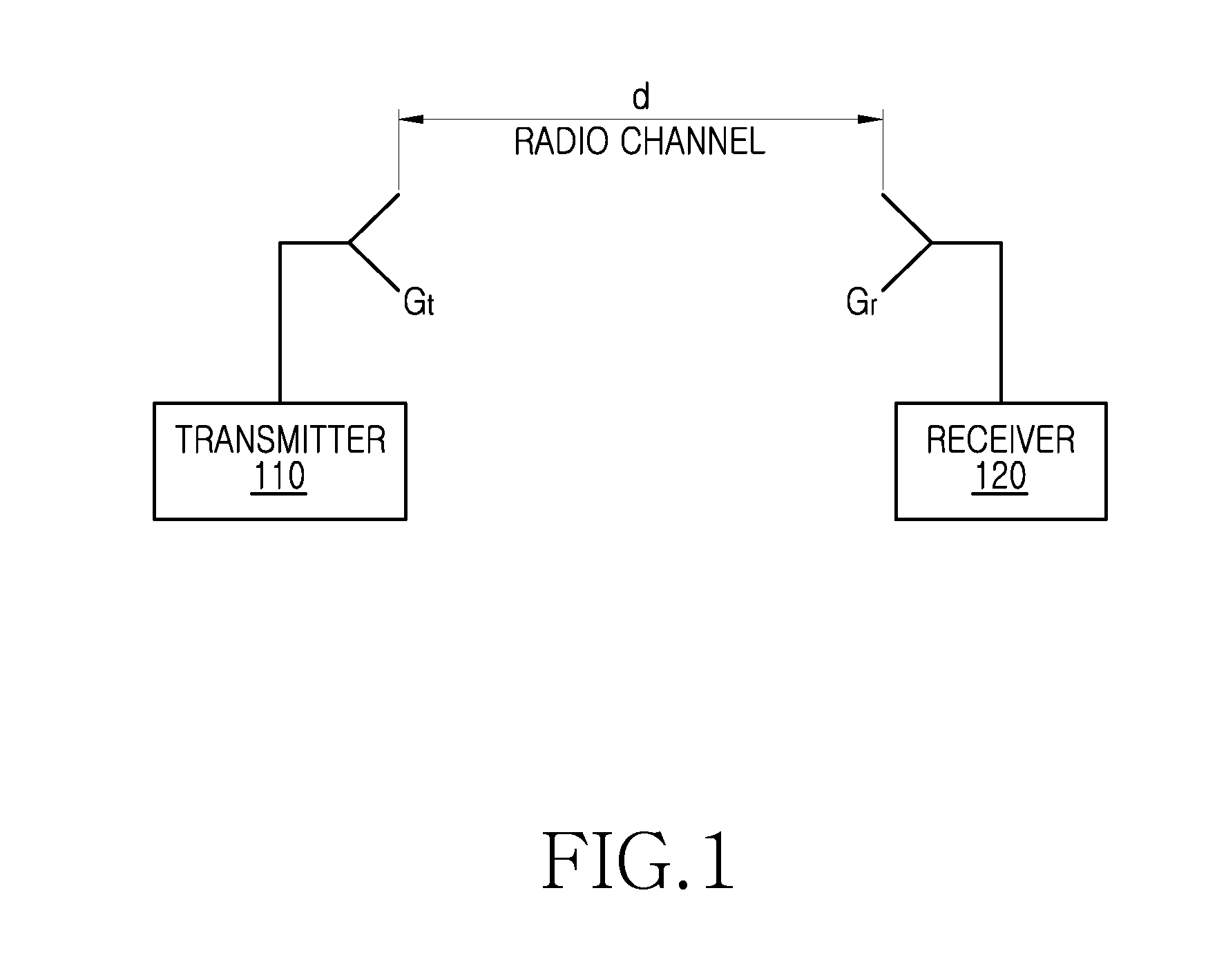
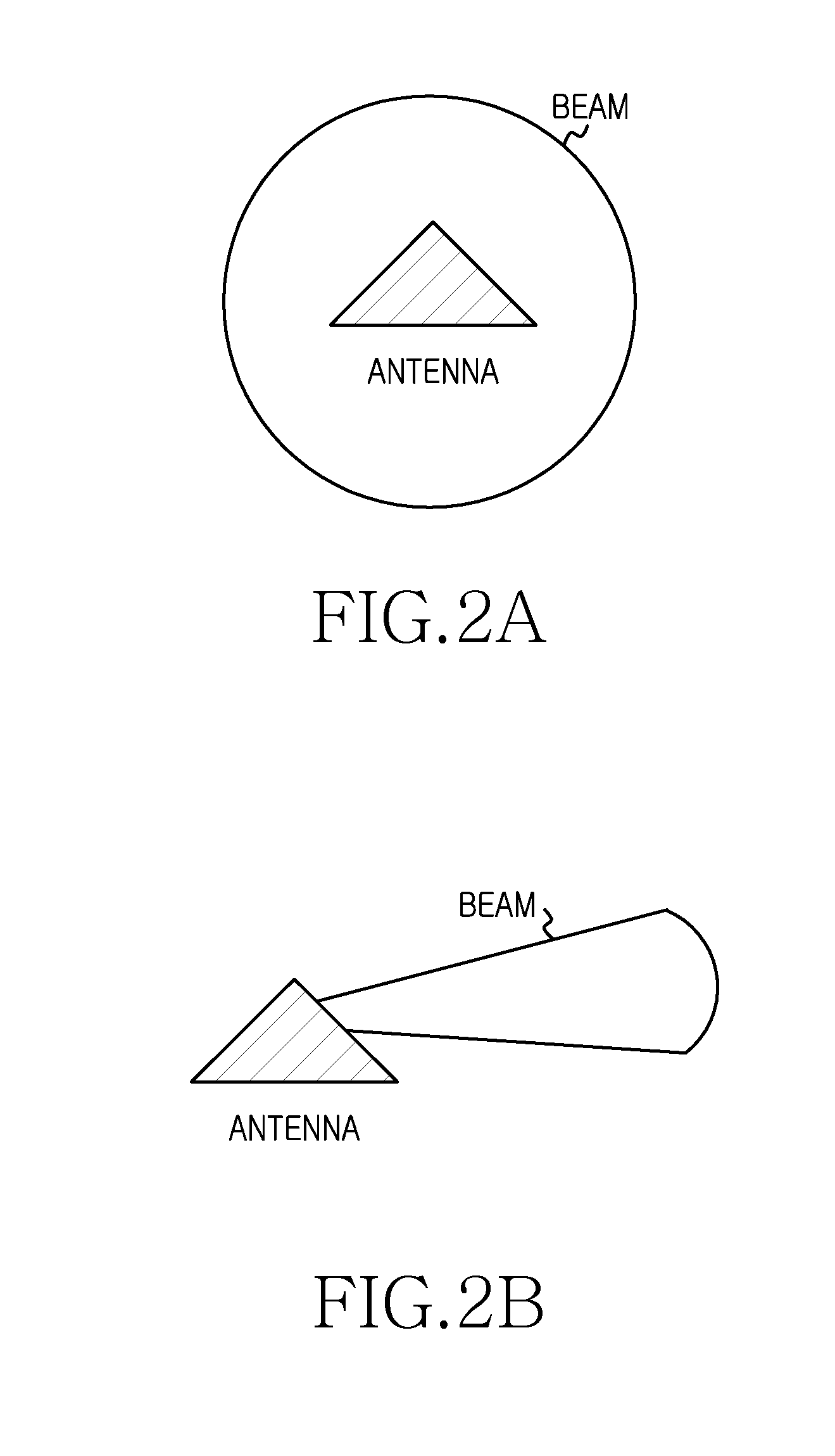
To retain a beam direction of beamforming in a wireless communication system, an apparatus for the beamforming includes a detector for measuring change of at least one of a movement and a motion of the apparatus; and a processor for determining a beam control parameter for aligning a beam direction with a counterpart apparatus by compensating for the change of the beam direction according to at least one of the movement and the motion.

Description


Claims


Application Information

Patent Timeline
Owner SAMSUNG ELECTRONICS CO LTD
Learn More