Train current collection mechanism

A technology for trains and electricity collection, applied in current collectors, power collectors, electric vehicles, etc., can solve problems such as poor power performance matching, affecting contact collection performance, and restricting rigid systems, etc., to achieve good contact collection The effect of electrical performance, superior performance and advanced technology

Pending Publication Date: 2019-03-19
SOUTHWEST JIAOTONG UNIV
View PDF0 Cites 2 Cited by
  • Summary
  • Abstract
  • Description
  • Claims
  • Application Information

AI Technical Summary

Problems solved by technology

Compared with the flexible system, the rigid system has obvious advantages such as simple structure, large carrying capacity, reliability and durability. Therefore, urban rails such as subways and light rails and maglev trains generally use the combination of power receiving shoes (collecting shoes) and third rails (power supply rails). A rigid system contact current collection method, but because the dynamic performance matching problem of the power receiving shoe (collecting shoe) and the third rail (power supply rail) structure has not been solved well, the shaking and vibration generated by the train during operation will pass through The power receiving shoe (collector shoe) is directly transmitted to the third rail (power supply rail), which not only generates noise, but also seriously affects the contact current collection performance between the power receiving shoe (collector shoe) and the third rail (power supply rail), thus seriously It restricts the good use of the advantages of the rigid system

Method used


Image

  • Train current collection mechanism
  • Train current collection mechanism
  • Train current collection mechanism

Examples


Embodiment 1

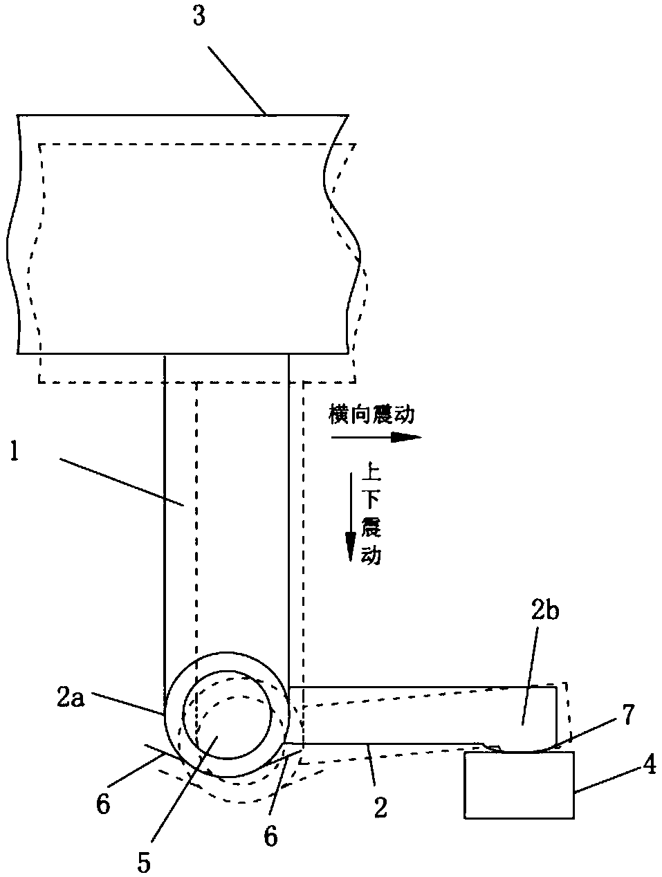
[0027] Such as figure 1 and figure 2 As shown, the embodiment of the present invention provides a train power collection mechanism, including a boot 1 and a power collection shoe 2, the top of the boot 1 is fixedly connected to the end of the longitudinal beam of the train bogie 3, and the bottom of the boot 1 The end is hinged with the connection end 2a of the collector shoe 2 through a fastener 5; the bottom of the free end 2b of the collector shoe 2 is provided with a contact portion 7 and contacts with the top of the power supply rail 4; the connection end of the collector shoe 2 2a is connected to the cable (not shown) leading to the traction drive system of the train; the bottom end of the boot 1 is provided with a limiting piece 6 for limiting the sagging angle and range of the collector shoe 2 . In the embodiment of the present invention, the boot 1 is an insulator, the collector shoe 2 is a conductor, the power supply rail 4 is arranged inside the boot 1, and the fa...

Embodiment 2

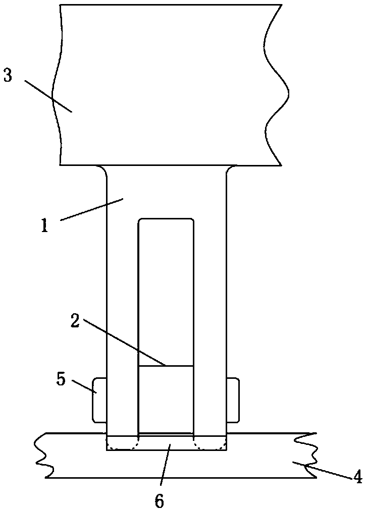
[0031] Such as Figure 4 As shown, the embodiment of the present invention provides a train power collection mechanism, including a boot 1 and a power collection shoe 2, the top of the boot 1 is fixedly connected to the end of the longitudinal beam of the train bogie 3, and the bottom of the boot 1 The end is hingedly connected to the connecting end 2a of the collector shoe 2 through a fastener 5; the bottom of the free end 2b of the collector shoe 2 is downwards to the contact portion 7 and contacts the upper surface of the power supply rail 4; the collector shoe 2. The connecting end 2a is connected to the cable (not shown) leading to the traction drive system of the train; the bottom end of the boot 1 is provided with a limiting piece 6 for limiting the sagging angle and range of the collector shoe 2. In the embodiment of the present invention, the boot 1 is an insulator, the collector shoe 2 is a conductor, the power supply rail 4 is arranged inside the boot 1, and the fas...

Embodiment 3

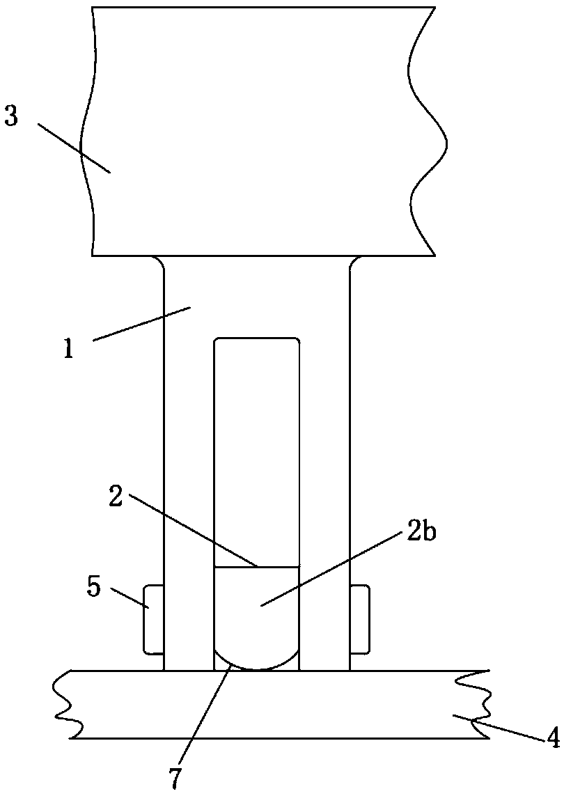
[0035] Combined with the above-mentioned second embodiment Figure 4 and the embodiment of the present invention Figure 6As shown, the embodiment of the present invention provides a train power collection mechanism, including a boot 1 and a power collection shoe 2, the top of the boot 1 is fixedly connected to the end of the longitudinal beam of the train bogie 3, and the bottom of the boot 1 The end is hingedly connected to the connecting end 2a of the collector shoe 2 through a fastener 5; the bottom of the free end 2b of the collector shoe 2 is downwards to the contact portion 7 and contacts the top of the power supply rail 4; the collector shoe 2. The connecting end 2a is connected to the cable (not shown) leading to the traction drive system of the train; the bottom end of the boot 1 is provided with a limiting piece 6 for limiting the sagging angle and range of the collector shoe 2. In the embodiment of the present invention, the boot 1 is an insulator, the collector s...


PUM


Abstract

The invention discloses a train current collection mechanism, and relates to the field of rail traffic and magnetic-levitation train power supply. The train current collection mechanism comprises a bootleg and a collector shoe, the top end of the bootleg is fixedly connected with a train bogie, the bottom end of the bootleg is connected with a connecting end of the collector shoe in a hinged manner through a pin, a contact portion is arranged at the bottom of a free end of the collector shoe and contacts with the top of a power supply rail, the connecting end of the collector shoe is connectedwith a cable leading to a train traction drive system, and a limit piece is arranged at the bottom end of the bootleg. Therefore, transverse vibration generated in running of rail traffic and a magnetic-levitation train and negative effects of up and down vibration on current collection performances can be eliminated, the advantages of a rigid system can be more effectively taken, and the train current collection mechanism is suitable for high-speed running.

Description

technical field [0001] The invention relates to the field of power supply for rail transit trains and maglev trains, in particular to a train power collection mechanism. Background technique [0002] The electric train adopts the contact current collection (power receiving) method of the pantograph and the catenary, where the catenary is divided into a flexible catenary and a rigid catenary. Mainline railways mostly use pantograph and flexible catenary. In addition to pantograph and flexible catenary, urban rails also use pantograph and rigid catenary. In addition, there are power shoes (collector shoes) Contact with the third rail (supply rail) to collect electricity. As the name suggests, the flexible catenary is a flexible system, while both the third rail and the rigid catenary are rigid systems. In addition to the contact pressure of the pantograph, the flexible system usually bears a lot of tension, while the rigid system only bears the contact pressure and almost no...

Claims


Application Information

Patent Timeline
Patent Type & Authority Applications(China)
IPC IPC(8): B60L5/39
CPCB60L5/39
Inventor 李群湛李书谦
Owner SOUTHWEST JIAOTONG UNIV
Why Eureka
Try Eureka