
Side screen splicing deductive system

A deduction system and side screen technology, applied in the direction of instruments, electrical digital data processing, digital output to display equipment, etc., can solve the problem that the deduction system cannot attract the audience, the publicity effect is not good, the deduction effect cannot be achieved, the impact of the picture, Insufficient attractiveness and other issues to achieve the effect of rich multimedia content

Pending Publication Date: 2019-03-19
上海摩奇贝斯展示设计营造有限公司
View PDF5 Cites 3 Cited by
  • Summary
  • Abstract
  • Description
  • Claims
  • Application Information

AI Technical Summary

Problems solved by technology

[0002] The traditional deduction system usually uses a single LED screen or multiple splicing screens to deduce multimedia images through the spliced ​​large-screen display for customers to watch or manufacturers to promote. However, the deduction space and deduction content of this single deduction method are inevitably single. Insufficient impact and attractiveness, unable to achieve the desired interpretation effect
Even relevant technical personnel have to work hard on the quality resolution and the spatial shape of the splicing screen itself in order to improve the realism of the display screen in the display screen. However, due to the limitations of the existing splicing technology, even if it costs a lot, the ideal effect cannot be achieved. , leading to the failure of the existing deduction system to attract the audience enough and poor publicity effect

Method used


Image

  • Side screen splicing deductive system
  • Side screen splicing deductive system
  • Side screen splicing deductive system

Examples


specific Embodiment example 1

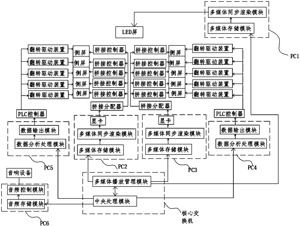
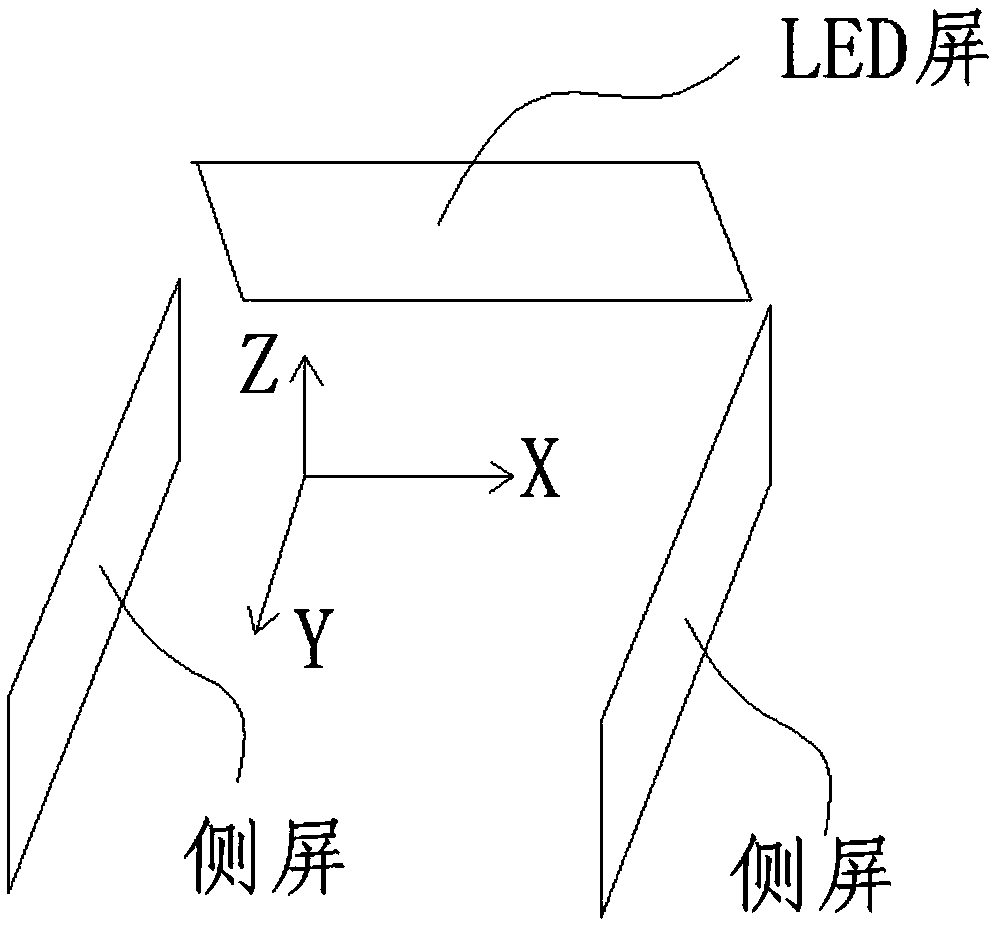
[0030]Side screen splicing interpretation system, including: LED screen, multiple side screens, splicing controller, splicing distributor, PC server, core switch; LED screen and multiple side screens are installed on the wall of the exhibition hall, and the two sides of the LED screen are parallel There are 6 side screens installed on the wall of the YOZ plane; the PC1 server includes a multimedia storage module and a multimedia synchronous rendering module connected to the multimedia storage module. The LED screen is connected to the multimedia synchronous rendering module in the PC1 server. Each side screen All are connected to an independent splicing controller, and the splicing controllers belonging to the same side are connected to the same splicing distributor, and each splicing distributor is connected to an independent PC2 server and PC3 server respectively, and both PC2 server and PC3 server include A graphics card, a multimedia synchronous rendering module connected t...

specific Embodiment example 2

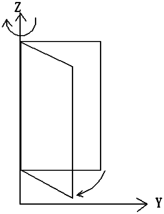
[0037] Side screen splicing interpretation system, including: LED screen, multiple side screens, splicing controller, splicing distributor, PC server, core switch; LED screen and multiple side screens are installed on the wall of the exhibition hall, and the side screens are The wall with a 15° inclination angle to the YOZ surface is installed close to the wall, and there are 6 side screens installed on both sides of the LED screen; the PC1 server includes a multimedia storage module, a multimedia synchronous rendering module connected to the multimedia storage module, and the LED screen and PC1 server Each side screen is connected to an independent splicing controller, and the splicing controllers belonging to the same side are all connected to the same splicing distributor, and each splicing distributor is connected to an independent PC2 server, The PC3 server is connected, the PC2 server and the PC3 server both include a graphics card, a multimedia synchronous rendering modu...


PUM


Abstract

A side screen splicing deductive system comprises an LED screen, a plurality of side screens, a splicing controller, a splicing distributor, a PC server, a core switch and an audio device; two rows ofside screens are symmetrically installed on both sides of the LED screen. The side screens are controlled by a splicing controller, a splicing distributor, and a PC server to play the same theme andcontent corresponding to the multimedia content. A plurality of PC servers are controlled by the same core exchange. A plurality of side screens are inverted at a certain angle under the control of aninverting driving device. Through the interaction between the LED panel and the rotatable side panel, the traditional plane deductive space is transformed into three-dimensional or thinking display space, which enables the audience to experience the reality and novelty experience, greatly improves the enthusiasm of the audience to visit, enables the audience to appreciate the rapid development ofmodern science and technology while deepening the audience's impression of the deductive picture, and greatly improves the deductive propaganda effect.

Description

technical field [0001] The invention relates to the technical field of exhibition hall systems, in particular to a side screen splicing and interpretation system. Background technique [0002] The traditional deduction system usually uses a single LED screen or multiple splicing screens to deduce multimedia images through the spliced ​​large-screen display for customers to watch or manufacturers to promote. However, the deduction space and deduction content of this single deduction method are inevitably single. The impact and attractiveness are not enough, and the expected interpretation effect cannot be achieved. Even relevant technical personnel have to work hard on the quality resolution and the spatial shape of the splicing screen itself in order to improve the realism of the display screen in the display screen. However, due to the limitations of the existing splicing technology, even if it costs a lot, the ideal effect cannot be achieved. , leading to the failure of t...

Claims


Application Information

Patent Timeline
IPC IPC(8): G06F3/14
CPCG06F3/1446
Inventor 朱利民
Owner 上海摩奇贝斯展示设计营造有限公司
Learn More