Pulled core oblique roof structure and injection mold

A technology of sloping roof and sloping roof group, which is applied in the field of injection molds, can solve the problems of difficult production and installation, damage of ribs and fixed blocks, and complex mold structure, so as to achieve ingenious structural design, reduce mold opening time, and improve The effect of production efficiency

Pending Publication Date: 2019-03-22
青岛海泰科模具有限公司
View PDF0 Cites 4 Cited by
  • Summary
  • Abstract
  • Description
  • Claims
  • Application Information

AI Technical Summary

Problems solved by technology

Due to the existence of multiple undercuts, it is necessary to withdraw the undercuts before the mold is opened, so as to avoid the core-pulling from hitting the mold. If the inclined top does not withdraw from the undercuts, it will cause ribs on the non-appearance surface of ...

Method used


Image

  • Pulled core oblique roof structure and injection mold
  • Pulled core oblique roof structure and injection mold
  • Pulled core oblique roof structure and injection mold

Examples


Embodiment 1

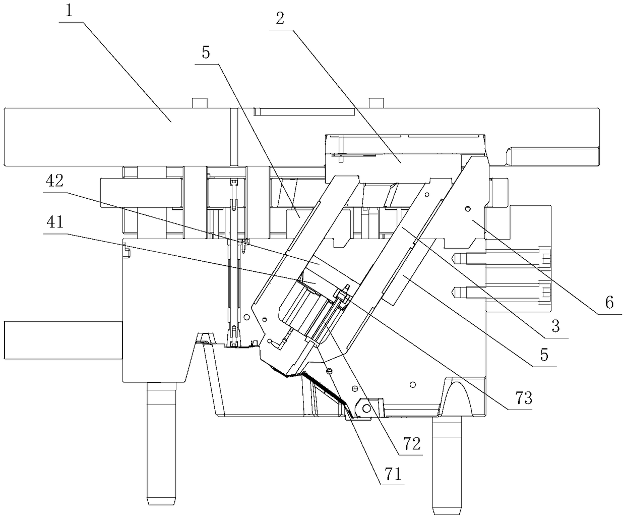
[0022] Embodiment 1, combining figure 1 and figure 2 , a core-pulling inclined roof structure, including a rear mold top plate 1 arranged on the outside of the rear mold, a core-pulling slide seat 2, a core-pulling seat 3 arranged in the rear mold, a core-pulling needle plate 4 and a guide block 5, the core-pulling The sliding seat 2 is fixedly installed on the rear mold top plate 1, and the rear mold top plate 1 is connected with the rear mold through a draw hook, and at the same time, the rear mold is connected with the front mold through the draw hook. The side adjacent to the core-pulling slide 2 and the core-pulling base 3 is provided with a chute, and one end of the core-pulling base 3 extends into the chute of the core-pulling slide 2 to slide and cooperate with it. When the mold moves, the core-pulling seat 3 is driven to move relative to the rear mold, and at the same time, the core-pulling seat 3 and the core-pulling slide seat 2 slide relative to each other. A we...

Embodiment 2

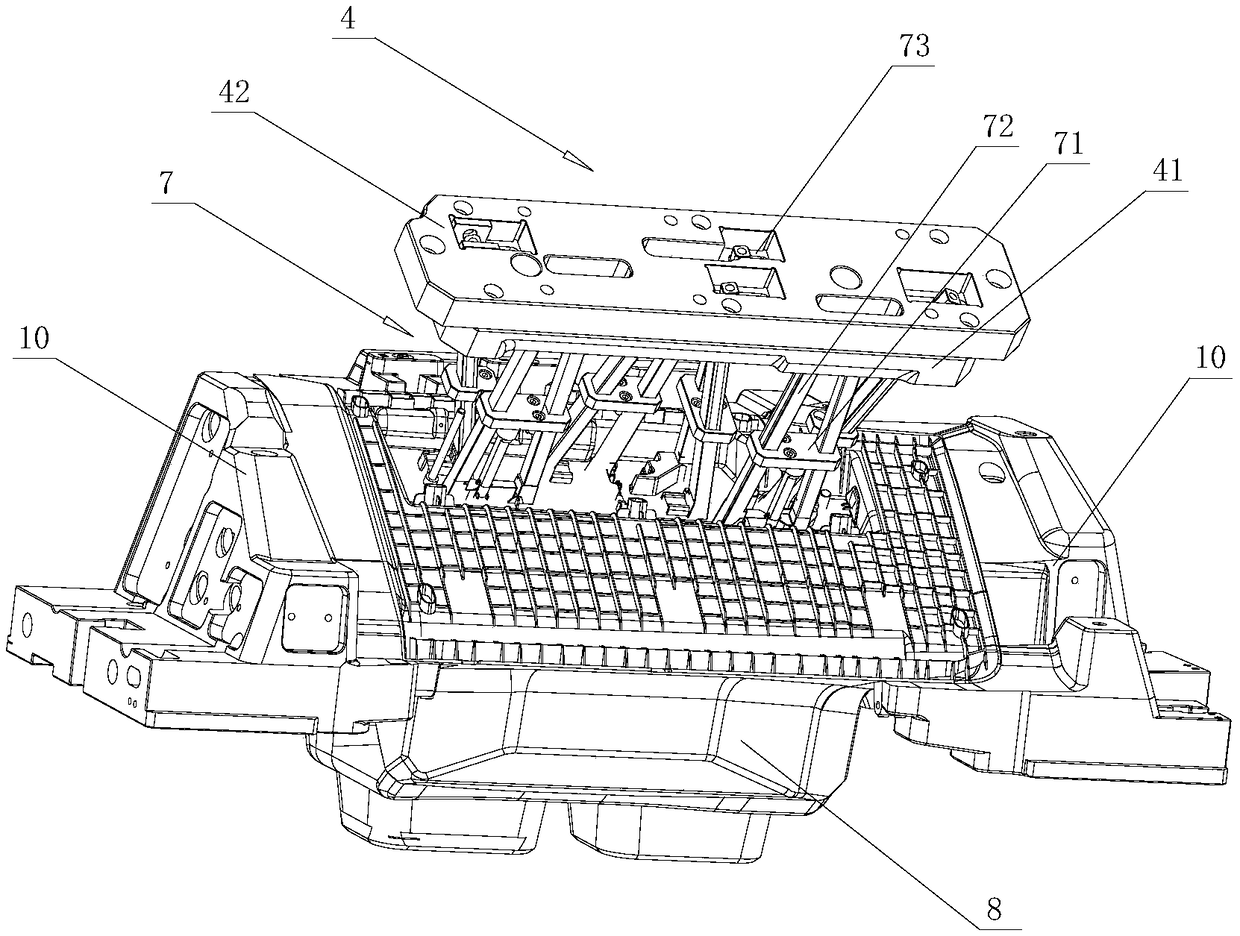
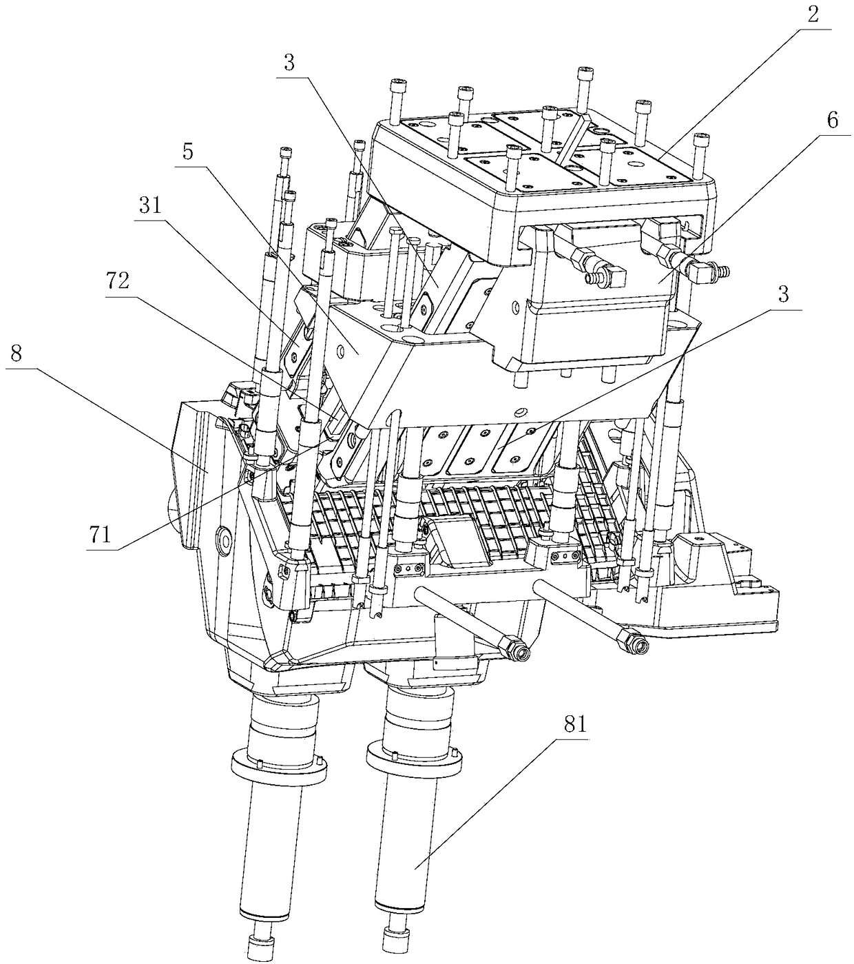
[0026] Example 2, combined with Figure 3 to Figure 5 , an injection mold, comprising a front mold, a back mold and a pull hook, characterized in that the back mold is provided with the above-mentioned core-pulling inclined roof structure, and the front mold is also provided with a front mold top block 8, and the front mold is provided with a The front mold ejector rod 81 that front mold top block 8 ejects from the front mold. Front mold is positioned at the both sides of its mold cavity, and two front mold slide blocks 10 are symmetrically arranged, and described front mold slide block 10 is slidably matched with front mold, and front mold slide block 10 is driven its movement by slide block oil cylinder, and front mold slide block 10 After opening the mold with the rear mold, after the two front mold sliders 10 move to both sides and withdraw from the undercut, the front mold top block 8 can eject the product from the front mold, and the ejected product remains in the front ...


PUM


Abstract

The invention discloses a pulled core oblique roof structure. The pulled core oblique roof structure comprises a rear mold top plate and a pulled core sliding base which are arranged on the outer sideof a rear mold, a pulled core base arranged inside the rear mold, a pulled core needle plate and a guide block. The pulled core sliding base is fixedly installed on the rear mold top plate. The rearmold top plate is connected with the rear mold through a drag hook. The rear mold is connected with a front mold through the drag hook. The guide block is fixedly installed inside the rear mold. The side wall of the pulled core base is in sliding fit with the guide block. One end of the pulled core base is slidingly connected with the pulled core sliding base. The pulled core needle plate is located on the inner side of the pulled core base and fixed to the rear mold. Multiple pulled core oblique roof sets are arranged on the pulled core needle plate. Each pulled core oblique roof set comprises an oblique roof guide sliding block and one or more pulled core oblique roofs. One end of each pulled core oblique roof is in movable connection with the pulled core needle plate. Each oblique roofguide sliding block is fixedly connected with the pulled core base. A pulled core oblique roof in the same set is driven to move by the corresponding oblique roof guide sliding block. The invention further discloses an injection mold. According to the pulled core oblique roof structure and the injection mold, the structural design is ingenious; the fabricating cost is lowered; the mold opening time is reduced; production efficiency is improved; and the rate of finished products is high.

Description

technical field [0001] The invention relates to the technical field of injection molds, in particular to a core-pulling inclined roof structure and an injection mold. Background technique [0002] The automotive glove box is made of PC+ABS material and molded by integral injection molding. After the glove box is formed in the mold, due to the undercut structure, it is necessary to set a core pull in the rear mold. In addition, the non-appearance surface of the glove box has many There are also many undercuts on the ribs. Before the front mold and the rear mold are opened, it is necessary to pull the core to exit the undercut, and the inclined top on the rib to exit the undercut. Due to the existence of multiple undercuts, it is necessary to withdraw the undercuts before the mold is opened, so as to avoid the core-pulling from hitting the mold. If the inclined top does not withdraw from the undercuts, it will cause ribs on the non-appearance surface of the glove box and fixe...

Claims


Application Information

Patent Timeline
IPC IPC(8): B29C45/33B29C45/44
CPCB29C45/33B29C45/4435
Inventor 李方方刘川东袁涛王洪波孙文强王纪学
Owner 青岛海泰科模具有限公司
Why Eureka
Try Eureka